AIGxG User Manual
UHV Bayard-Alpert Ion Gauge
- Installation
- Ion Gauge Cables
- Ion Gauge Operation
- Filament Replacement
- Repair and Refurbishment
- Gas Correction Factors
- Assistance
Installation
Inspect the gauge structure before removing from the moulded clear plastic packing. Report any obvious damage to your AML Distributor before opening the moulded packing. Save the packing material, including the small foam plastic piece which restrains the flange in the mould.
It is assumed that the user is familiar with the use of Conflat® flanges and copper gaskets. Appropriate handling techniques must be used to avoid contamination of the gauge head. Avoid straining the feedthrough pins, as this may cause a leak.
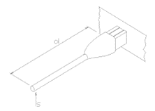
Mount the gauge head in a position where the free electrons generated in its vicinity will not affect other equipment. The gauge head is intended to be inserted so that the entire grid structure is inside the chamber: should any part of it remain inside the tube behind the mounting flange the sensitivity of the gauge head will be altered. The orientation of the gauge head should be such that the filaments are to the side of, or below, the grid structure. This will ensure that if the filament should sag or break it will not short-circuit to the grid. It is desirable that the feedthrough pins point sideways or upward so that the weight of the connector and cable do not tend to pull the connector off the pins.
 |
|
 |
|
| No | Yes | Yes | No |


The performance of the ion gauge may be affected by other electron or ion generating processes within the vacuum chamber: should shielding of the gauge head be necessary, ensure that the conductance between the gauge head and volume of interest is not significantly decreased by its presence. Any grounded shield will affect the electron dynamics in the gauge head and hence its sensitivity: this can be minimised by locating the shield as far away as is convenient.
When this gauge is used in conjunction with an AML NGC3 Ion Gauge Controller, both the gauge and controller are protected from all normal failure modes of either. Users should be aware of potential hazards from other equipment, however, particularly those introducing high voltages into the vacuum chamber (X ray sources for example). As a direct discharge from one of these at high pressure may cause extensive damage, shielding should always be introduced in such cases.
Ion Gauge Cables
WARNING! The use of AML AIGLx cables is essential to achieve compliance with the EC EMC Directive, 89/336/EEC using AML and similar controllers. Extension cables are not recommended as these will prejudice compliance. 3, 6 and 9 metre cables are available, models AIGL3, AIGL6 and AIGL9, respectively.
 |
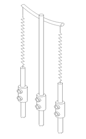
The composite cables are heavy and require to be strain-relieved near both ends. This can be achieved by supporting the cable with ties at points 's' shown in the diagrams. Distance 'd' should be between 20 and 50cm. The cable should be slack between the tie and the connector. In bakeout zones stainless-steel cable ties should be used. |
 |
At the instrument end of the cable the connector pins 'float' inside the moulding. Always support and align the cable at the rear of the connector when inserting it into the controller connector as a misaligned pin may be damaged if forced. The green and yellow flying ground lead must be connected to the M5 ground stud on the rear panel of the NGC3. |
Ion Gauge Operation
New gauges must be operated carefully to achieve good results and long filament life. The filaments are under tension when new: run both filaments for a few seconds in emission to reduce and equalise the tension. Operate at low emission current in order to outgas them fully before increasing the emission current. Do not subject the gauge to electron- bombardment degas until it has run at the highest emission current available and the resultant pressure burst has fully subsided.
The signal current from a BA gauge at UHV is very small and can easily be disturbed.
Do not allow the cable to be moved in use as this will induce currents and generate piezoelectric and triboelectric charges which can affect UHV measurements for several seconds.
Ensure that the front face of the AIGLx ion gauge connector is kept clean, since effective insulation resistances of the order of 1016 ohms are required. Isopropyl alcohol or CFC on a clean lint-free swab may be used to remove fingerprints or dirt. These solvents do not affect the PEEK housing of the connector.
The nominal bias conditions and sensitivity for this gauge are given in the table below. AML and similar controllers provide these bias voltages.
Recommended operating conditions
|
|
Emission |
Degas |
|
Collector |
+0V |
+0V |
|
Grid |
+200V |
+500V |
|
Filament bias |
+50V |
+0V |
|
Maximum Emission Current |
10mA |
100mA Tungsten 60mA Thoriated |
Filament Replacement
Tungsten filaments have an emission life of one to three years in UHV. The life will be dependent on the residual gases present, range of pressures and vibration coupled to the filament. Tungsten filaments become brittle in use and the most common causes of failure are mechanical or thermal shocks. If the gauge head is to be moved to another location it is advisable to replace the filament assembly.
Replacement filament assemblies are available from AML distributors at low cost. The filament assemblies are fixed to the feedthrough assembly by barrel connectors and Allen-headed set screws. An Allen key is provided with each replacement filament assembly. A pair of long-nosed pliers, side cutters, cleanroom gloves, cotton buds and some isopropyl alcohol are required.
 |
Clean the jaws of the cutters and pliers with alcohol. Swab some alcohol onto the set screws to lubricate them. Support the feedthrough wire with the long-nosed pliers close to the barrel connector and loosen the screw holding the filament support. This is the screw furthest away from the feedthrough flange. Loosen the screws on all three supports and remove the old filament assembly. Remove the restraining sleeve from the new assembly. Fit the centre support of the new assembly into the barrel connector and tighten the screws. Hold each of the filament terminations in turn with the pliers and extend them down to the outer barrel connectors. Fix them in place with the set screws. Ensure that the centre support of the filament assembly is parallel to the gauge axis and approximately 3mm from the side of the grid. |
Repair and Refurbishment
Other than gauge heads returned under warranty it is generally not economically feasible to return damaged gauges for repair. Leaking feedthroughs cannot be repaired. Distorted grid structures and failed filaments are readily repairable by users.
Any gauge head returned to AML must be accompanied by a signed statement by the user stating clearly the nature of any toxic or radioactive material used in its operating environment and the means taken to ensure any contamination is removed.
Ensure that gauge heads are properly packed in original AML packing.
Gas Correction Factors
Gas correction factor tables are are only reproduced for the convenience of the user and do not imply that use with other gases will be safe with BA ion gauges.
Divide sensitivity by 100 for Pa-1; multiply by 1.33 for Torr-1.
|
Gas |
Symbol |
Gas Correction Factor |
NGC Sensitivity S, mBar-1 |
|
Acetone |
(CH3)2CO |
3.6 |
68 |
|
Air |
--- |
1.0 |
19 |
|
Ammonia |
NH3 |
1.3 |
25 |
|
Argon |
Ar |
1.3 |
24 |
|
Benzene |
C6H6 |
5.9 |
112 |
|
Bromine |
Br |
3.8 |
72 |
|
Bromomethane |
CH3Br |
3.7 |
70 |
|
Cadmium |
Cd |
2.3 |
44 |
|
Carbon Dioxide |
CO2 |
1.4 |
27 |
|
Carbon Disulfide |
CS2 |
5.0 |
95 |
|
Carbon Monoxide |
CO |
1.05 |
20 |
|
Carbon Tetrachloride |
CCl4 |
6.0 |
114 |
|
Cesium |
Cs |
4.3 |
82 |
|
Chlorine |
CI2 |
0.68 |
13 |
|
Chlorobenzene |
C6H5CI |
7.0 |
133 |
|
Chloroethane |
C2H5CI |
4.0 |
76 |
|
Chloroform |
CHCI3 |
4.7 |
89 |
|
Chloromethane |
CH3CI |
2.6 |
49 |
|
Cyanogen |
(CN)2 |
2.8 |
53 |
|
Cyclohexylene |
C6H12 |
7.9 |
150 |
|
Deuterium |
D2 |
0.35 |
7 |
|
Dichlorodifloromethane |
CCI2F2 |
2.7 |
51 |
|
Dichloromethane |
CH2CI2 |
3.7 |
70 |
|
Ethane |
C2H6 |
2.6 |
49 |
|
Ethanol |
C2H5OH |
3.6 |
68 |
|
Ethyl Acetate |
CH3COOC2H5 |
5.0 |
95 |
|
Ethyl ether |
(C2H5)2O |
5.1 |
97 |
|
Ethylene |
C2H4 |
2.3 |
44 |
|
Ethylene oxide |
(CH2)2O |
2.5 |
47 |
|
Helium |
He |
0.18 |
3 |
|
Heptane |
C7H16 |
8.6 |
163 |
|
Hexane |
C6H14 |
6.6 |
|
|
Hydrogen |
H2 |
0.46 |
9 |
|
Hydrogen Bromide |
HBr |
2.0 |
38 |
|
Hydrogen Chloride |
HCl |
1.5 |
28 |
|
Hydrogen Cyanide |
HCN |
1.5 |
28 |
|
Hydrogen Fluoride |
HF |
1.4 |
27 |
|
Hydrogen Iodide |
HI |
3.1 |
59 |
|
Hydrogen Sulfide |
H2S |
2.2 |
42 |
|
Iodine |
I2 |
5.4 |
103 |
|
Iodomethane |
CH3I |
4.2 |
80 |
|
Isoamyl Alcohol |
C5H11OH |
2.9 |
55 |
|
Isobutylene |
C4H8 |
3.6 |
68 |
|
Krypton |
Kr |
1.9 |
36 |
|
Lithium |
Li |
1.9 |
36 |
|
Mercury |
Hg |
3.6 |
68 |
|
Methane |
CH4 |
1.4 |
27 |
|
Methanol |
CH3OH |
1.8 |
34 |
|
Methtyl Acetate |
CH3COOCH3 |
4.0 |
76 |
|
Mythyl ether |
(CH3)2O |
3.0 |
57 |
|
Naphthalene |
C10H8 |
9.7 |
184 |
|
Neon |
Ne |
0.3 |
6 |
|
Nitrobenzene |
C6H5NO2 |
7.2 |
137 |
|
Nitric Oxide |
NO |
1.3 |
25 |
|
Nitrogen |
N2 |
1.0 |
19 |
|
Nitrogen Oxide |
NO2 |
1.2 |
23 |
|
Nitrous Oxide |
N2O |
1.5 |
28 |
|
Oxygen |
O2 |
1.0 |
19 |
|
Phosphine |
PH3 |
2.6 |
49 |
|
Potassium |
K |
3.6 |
68 |
|
Propane |
C3H8 |
4.2 |
80 |
|
Rubidium |
Rb |
4.3 |
82 |
|
Sodium |
Na |
3.0 |
57 |
|
Sulphur Dioxide |
SO2 |
2.1 |
40 |
|
Sulphur Hexafluoride |
SF6 |
2.3 |
44 |
|
Toluene |
C6H5CH3 |
6.8 |
129 |
|
Water |
H2O |
1.1 |
21 |
|
Xenon |
Xe |
2.9 |
55 |
Assistance
In the first instance, contact the distributor or supplier of the equipment. Always quote the serial number of the instrument and firmware and software versions. Provide a written description of the problem. If the problem is related to a motor or mechanism manufactured by AML, include the serial number(s) of those items. Do not return products to AML without prior approval.
Arun Microelectronics Ltd
Tel: +44 (0)1903 884141
Email: info@arunmicro.com
Website: arunmicro.com