| [](https://bookstack.vps-da8d40f3.arunmicro.com/uploads/images/gallery/2024-01/aig1.png) | [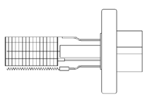](https://bookstack.vps-da8d40f3.arunmicro.com/uploads/images/gallery/2024-01/aig2.png) | [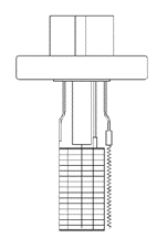](https://bookstack.vps-da8d40f3.arunmicro.com/uploads/images/gallery/2024-01/aig3.png) | [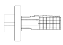](https://bookstack.vps-da8d40f3.arunmicro.com/uploads/images/gallery/2024-01/aig4.png) |
| No | Yes | Yes | No |
**WARNING!** The use of AML AIGLx cables is essential to achieve compliance with the EC EMC Directive, 89/336/EEC using AML and similar controllers. Extension cables are not recommended as these will prejudice compliance. 3, 6 and 9 metre cables are available, models AIGL3, AIGL6 and AIGL9, respectively.
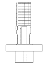
| [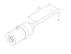](https://bookstack.vps-da8d40f3.arunmicro.com/uploads/images/gallery/2024-01/aig-cable1.png) | The composite cables are heavy and require to be strain-relieved near both ends. This can be achieved by supporting the cable with ties at points 's' shown in the diagrams. Distance 'd' should be between 20 and 50cm. The cable should be slack between the tie and the connector. In bakeout zones stainless-steel cable ties should be used. |
| [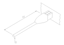](https://bookstack.vps-da8d40f3.arunmicro.com/uploads/images/gallery/2024-01/aig-cable2.png) | At the instrument end of the cable the connector pins 'float' inside the moulding. Always support and align the cable at the rear of the connector when inserting it into the controller connector as a misaligned pin may be damaged if forced. The green and yellow flying ground lead must be connected to the M5 ground stud on the rear panel of the NGC3. |
| Emission | Degas | |
| Collector | +0V | +0V |
| Grid | +200V | +500V |
| Filament bias | +50V | +0V |
| Maximum Emission Current | 10mA | 100mA Tungsten 60mA Thoriated |
| [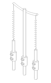](https://bookstack.vps-da8d40f3.arunmicro.com/uploads/images/gallery/2024-01/aig-fil-assy.png) | Clean the jaws of the cutters and pliers with alcohol. Swab some alcohol onto the set screws to lubricate them. Support the feedthrough wire with the long-nosed pliers close to the barrel connector and loosen the screw holding the filament support. This is the screw furthest away from the feedthrough flange. Loosen the screws on all three supports and remove the old filament assembly. Remove the restraining sleeve from the new assembly. Fit the centre support of the new assembly into the barrel connector and tighten the screws. Hold each of the filament terminations in turn with the pliers and extend them down to the outer barrel connectors. Fix them in place with the set screws. Ensure that the centre support of the filament assembly is parallel to the gauge axis and approximately 3mm from the side of the grid. |
| Gas | Symbol | Gas Correction Factor | NGC Sensitivity S, mBar-1 |
| Acetone | (CH3)2CO | 3.6 | 68 |
| Air | --- | 1.0 | 19 |
| Ammonia | NH3 | 1.3 | 25 |
| Argon | Ar | 1.3 | 24 |
| Benzene | C6H6 | 5.9 | 112 |
| Bromine | Br | 3.8 | 72 |
| Bromomethane | CH3Br | 3.7 | 70 |
| Cadmium | Cd | 2.3 | 44 |
| Carbon Dioxide | CO2 | 1.4 | 27 |
| Carbon Disulfide | CS2 | 5.0 | 95 |
| Carbon Monoxide | CO | 1.05 | 20 |
| Carbon Tetrachloride | CCl4 | 6.0 | 114 |
| Cesium | Cs | 4.3 | 82 |
| Chlorine | CI2 | 0.68 | 13 |
| Chlorobenzene | C6H5CI | 7.0 | 133 |
| Chloroethane | C2H5CI | 4.0 | 76 |
| Chloroform | CHCI3 | 4.7 | 89 |
| Chloromethane | CH3CI | 2.6 | 49 |
| Cyanogen | (CN)2 | 2.8 | 53 |
| Cyclohexylene | C6H12 | 7.9 | 150 |
| Deuterium | D2 | 0.35 | 7 |
| Dichlorodifloromethane | CCI2F2 | 2.7 | 51 |
| Dichloromethane | CH2CI2 | 3.7 | 70 |
| Ethane | C2H6 | 2.6 | 49 |
| Ethanol | C2H5OH | 3.6 | 68 |
| Ethyl Acetate | CH3COOC2H5 | 5.0 | 95 |
| Ethyl ether | (C2H5)2O | 5.1 | 97 |
| Ethylene | C2H4 | 2.3 | 44 |
| Ethylene oxide | (CH2)2O | 2.5 | 47 |
| Helium | He | 0.18 | 3 |
| Heptane | C7H16 | 8.6 | 163 |
| Hexane | C6H14 | 6.6 | 125 |
| Hydrogen | H2 | 0.46 | 9 |
| Hydrogen Bromide | HBr | 2.0 | 38 |
| Hydrogen Chloride | HCl | 1.5 | 28 |
| Hydrogen Cyanide | HCN | 1.5 | 28 |
| Hydrogen Fluoride | HF | 1.4 | 27 |
| Hydrogen Iodide | HI | 3.1 | 59 |
| Hydrogen Sulfide | H2S | 2.2 | 42 |
| Iodine | I2 | 5.4 | 103 |
| Iodomethane | CH3I | 4.2 | 80 |
| Isoamyl Alcohol | C5H11OH | 2.9 | 55 |
| Isobutylene | C4H8 | 3.6 | 68 |
| Krypton | Kr | 1.9 | 36 |
| Lithium | Li | 1.9 | 36 |
| Mercury | Hg | 3.6 | 68 |
| Methane | CH4 | 1.4 | 27 |
| Methanol | CH3OH | 1.8 | 34 |
| Methtyl Acetate | CH3COOCH3 | 4.0 | 76 |
| Mythyl ether | (CH3)2O | 3.0 | 57 |
| Naphthalene | C10H8 | 9.7 | 184 |
| Neon | Ne | 0.3 | 6 |
| Nitrobenzene | C6H5NO2 | 7.2 | 137 |
| Nitric Oxide | NO | 1.3 | 25 |
| Nitrogen | N2 | 1.0 | 19 |
| Nitrogen Oxide | NO2 | 1.2 | 23 |
| Nitrous Oxide | N2O | 1.5 | 28 |
| Oxygen | O2 | 1.0 | 19 |
| Phosphine | PH3 | 2.6 | 49 |
| Potassium | K | 3.6 | 68 |
| Propane | C3H8 | 4.2 | 80 |
| Rubidium | Rb | 4.3 | 82 |
| Sodium | Na | 3.0 | 57 |
| Sulphur Dioxide | SO2 | 2.1 | 40 |
| Sulphur Hexafluoride | SF6 | 2.3 | 44 |
| Toluene | C6H5CH3 | 6.8 | 129 |
| Water | H2O | 1.1 | 21 |
| Xenon | Xe | 2.9 | 55 |