D-Series UHV Stepper Motor User Manual
User manual for AML's D-series UHV stepper motors.
- Summary and Warnings
- Packing
- Installation
- Load Connection
- Vacuum Conditioning
- Drive Requirements
- Over-Temperature Protection
- Identifying and Connecting the Leads
- Feedthrough Requirements
- Preparation of Motor Leadout Wires for use with Other Feedthroughs
- Reversal of Rotation
- Troubleshooting
- General Operation Considerations for UHV-Compatible Motors
Summary and Warnings
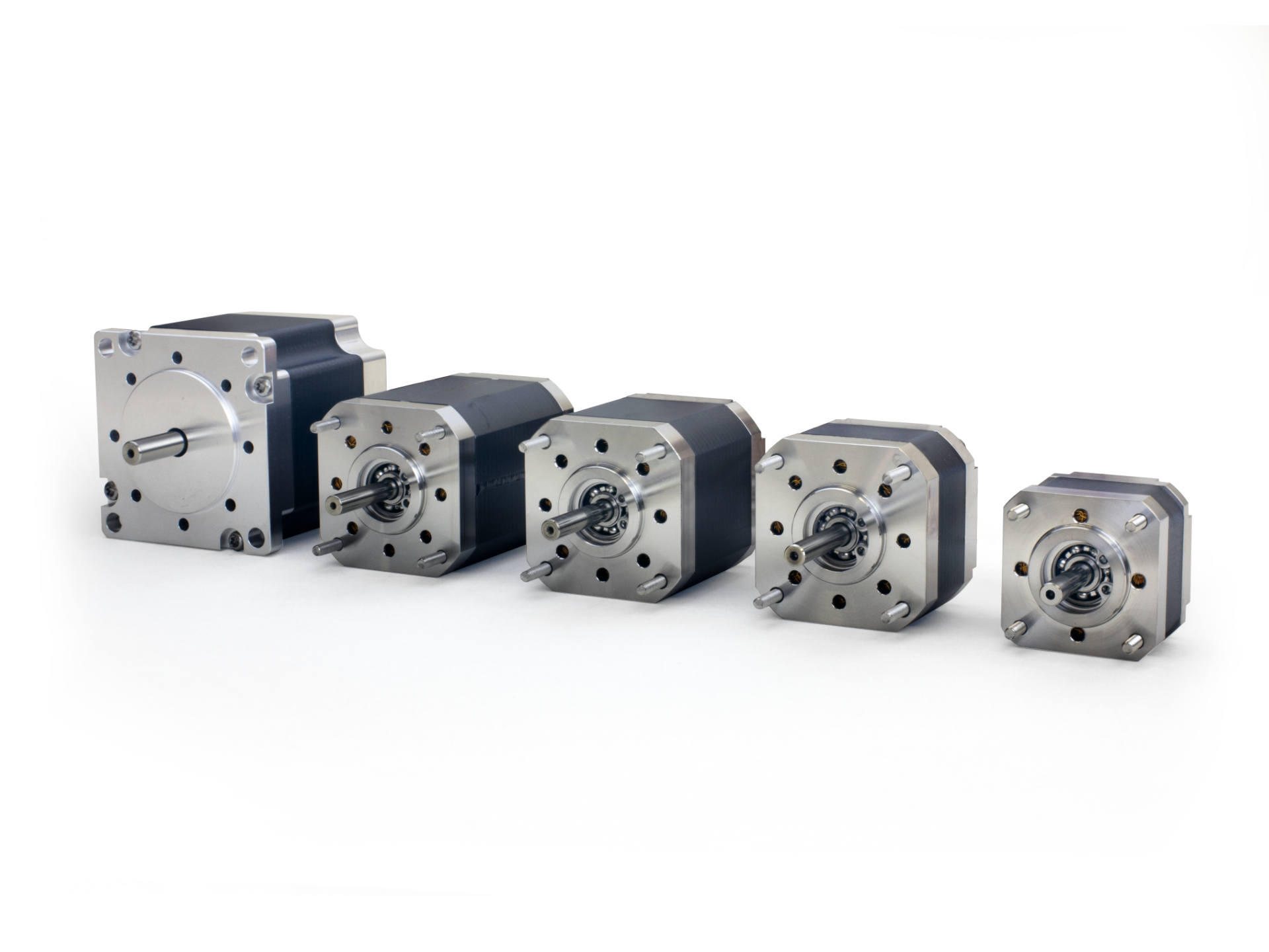
AML stepper motors are specifically designed for use in UHV environments making them ideally suited for low-speed precision
in-vacuum manipulation. The model D motors are two phase hybrid stepper motors, available in a range of standard sizes
and torque ratings. Standard motors provide 200 full steps per revolution, are suitable for use below 1x10⁻¹⁰ mBar and
temperatures between -65 °C to +190 °C. Extended low temperature range (-196 °C) and radiation hard versions (1 x 10⁶ Gy)
are available options.
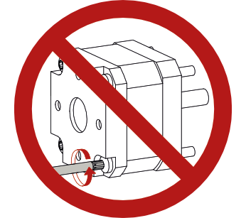
The mounting screws are fitted with metered torque. Do not disturb. Do not drop, demagnetise, disassemble, modify or
overheat the motor or allow particles to enter the bearings or pumping ports.
Do not touch the stepper motor with bare hands!
The published performance was obtained using an SMD210 drive operating with standard settings for step division. The
SMD210 is a bipolar, switch-mode, current-regulating drive, optimised for use with vacuum stepper motors. Different drives
will produce different speed/torque curves. Drives capable of producing a total phase current of more than 1A RSS (root sum
of squares) may damage the insulation, even if the current is claimed to be adjustable.
Design mechanisms with balanced rotating loads and/or friction to maintain position with reduced or zero phase current for
minimum outgassing. Use step division only to smooth transitions: increase resolution by reduction gearing.
Ensure ice cannot form in the motor if testing at low temperature in air. Avoid thermal shocks, for example, plunging in liquid
nitrogen.
Packing
AML motors are vacuum sealed packaged. Wear gloves to remove the motor from its vacuum packaging. Once removed it
must be stored in a cleanroom or clean, closed container.
Installation
Use the extended screws for mounting but do not adjust them. Take normal vacuum precautions, avoid creating trapped volumes when mounting the motor and obstruct as few as possible of the pumping holes in the end faces. The location spigot projecting from the face of the motor is accurately concentric with the shaft and intended for precise location in a recess.
Warranty is void if screws are tampered with.
Load Connection
The preferred method of coupling a load to the shaft is by a setscrew or collet fixing. AML do not recommend users modify shafts.
Vacuum Conditioning
Motors are supplied pre-baked to 200 °C in 1 x 10⁻⁶ mbar pressure for 24 hours and vented with dry Nitrogen before vacuum packaging. They may still adsorb water in storage and handling so a 24-hour bake by an AML stepper motor drive, with an adequate pump is recommended to achieve UHV-compatibility.
Drive Requirements
These motors are specifically designed for use in conjunction with AML stepper motor drives current-regulated switch-mode drive. If another drive is used it must be a bipolar 2-phase drive and capable of providing a selection of well-regulated currents of less than or equal to 1 Amp per phase. If the drive can provide simultaneous currents to both phases (for step division) then the root of the sum of the squares of the phase currents must never exceed 1 Amp.
The source voltage of alternative drives should be greater than 45 V. Lower voltages will result in loss of torque at higher stepping rates. Voltages over 100 V are not suitable for vacuum use. Switching frequencies should not exceed 22 kHz and peak-to-peak switching ripple on the phase current should not exceed 15%.
The drive current should be reduced or removed when the motor is stopped. For this reason, attempts to improve angular resolution by step division are not recommended.
Refer to the current motor datasheet for electrical, mechanical and thermal characteristics.
Over-Temperature Protection
All AML motors are provided with a K-type Thermocouple (NiCr-Ni) embedded between adjacent windings as standard, or
alternatively, the PT100 temperature sensor option. The drive current must be removed when the indicated temperature of
the windings reaches 190 °C. AML drives provide this function. Simple on/off temperature controllers may be used but ensure
that the adverse electrical noise environment within the motor underdrive does not affect the temperature measurement.
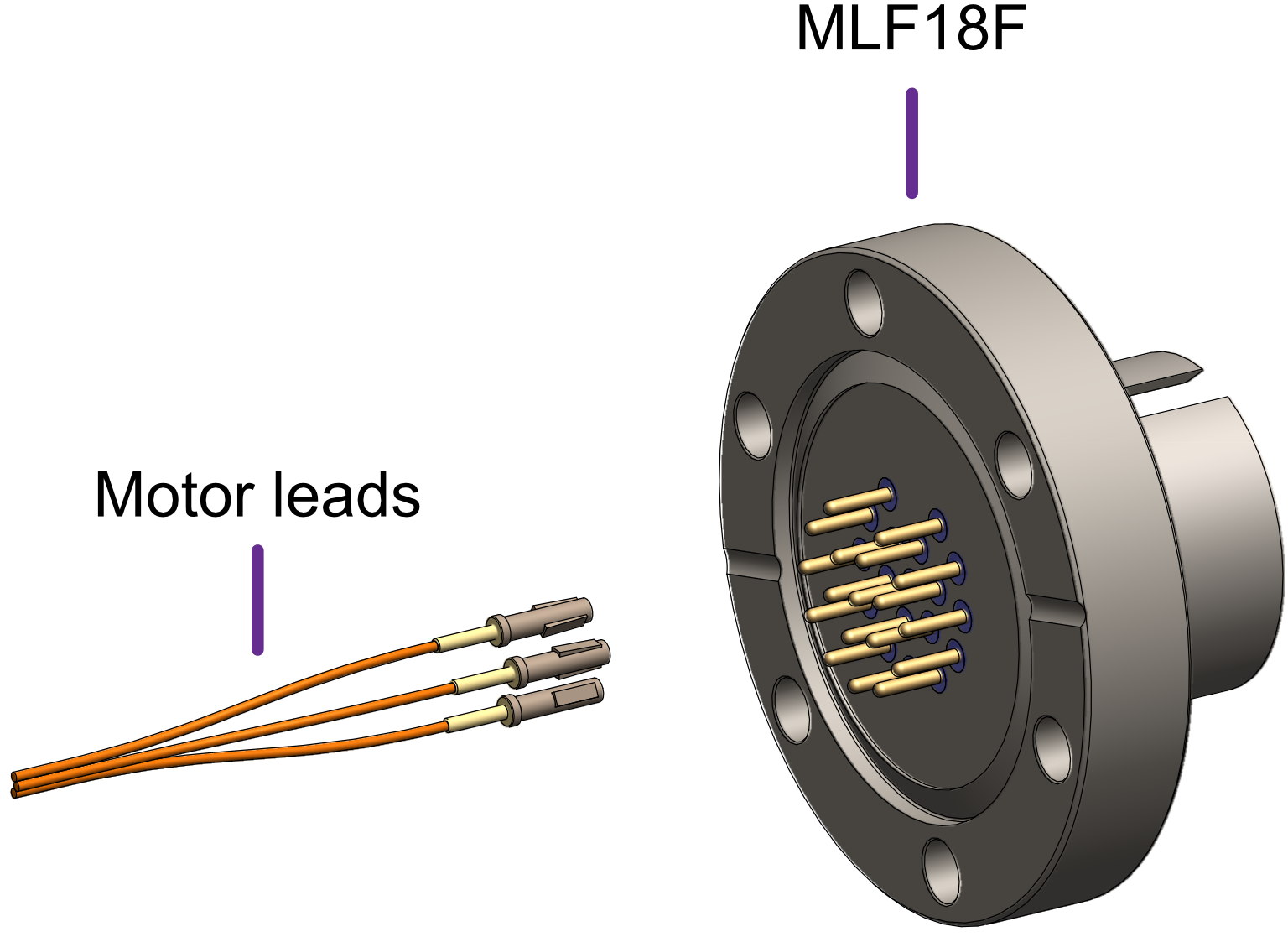
Identifying and Connecting the Leads
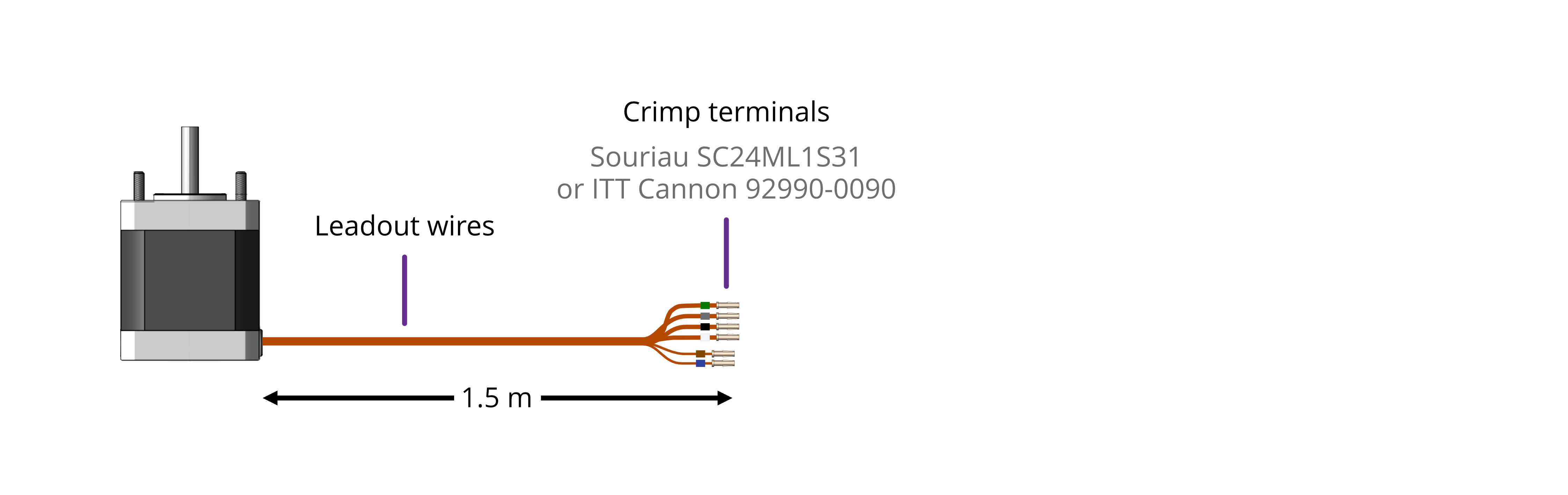
The lead-out wires are self-coloured polyimide film-wrapped, silver-plated OFHC copper and each is fitted with a 1.5 mm crimp socket terminal. They are supplied fitted with UHV compatible coloured glass beads for identification. Lead-out wires are supplied 1.5 metres long but can be shortened if required. For replacement crimp terminals use Souriau SC24ML1S31
(AML part no. MLF18SKT) or equivalent.
If the identification beads have been removed, then use the following procedure. An ohmmeter with resolution down to about 1 ohm is required to identify the two phase windings: most inexpensive multimeters are suitable.
The phase lead-out wires are much thicker than the temperature sensor wires. Radiation-hard motors may have multi-strand leads. Identify the two motor phases by their resistance, which will be in the range of 3 to 15 ohms, depending on the motor type. There is no electrical connection between the two phases or to the temperature sensor or the case of the motor.
Most of the resistance is in the windings of the motor and is virtually unaffected by shortening of the leads. Connect each phase to the appropriate drive terminals. The resistance of the wires from the feedthrough to the drive must be less than a few ohms.
The thermocouple wires are much thinner than the phase leads. The thermocouple is insulated from the rest of the motor. The Alumel wire may be identified with a magnet since it is weakly magnetic. At the controller the Alumel lead should be connected to the terminal marked Alumel, N, -, or coloured blue, and the Chromel lead should be connected to the terminal marked Chromel, P, + or coloured brown. The temperature measurement is not required to be very precise, so it is not necessary to use thermocouple-compatible feedthroughs or extension wires. If compatible materials are used then they must be connected the correct way round.
Standard Wiring: |
Option P Wiring: |
 |
 |
Feedthrough Requirements
Motor wiring
Overview
Connecting motors inside a vacuum chamber to the SMD4 comprises two tasks:
-
Wiring the motor to a vacuum feedthrough installed in the chamber wall.
-
Wiring the vacuum feedthrough to the SMD4.
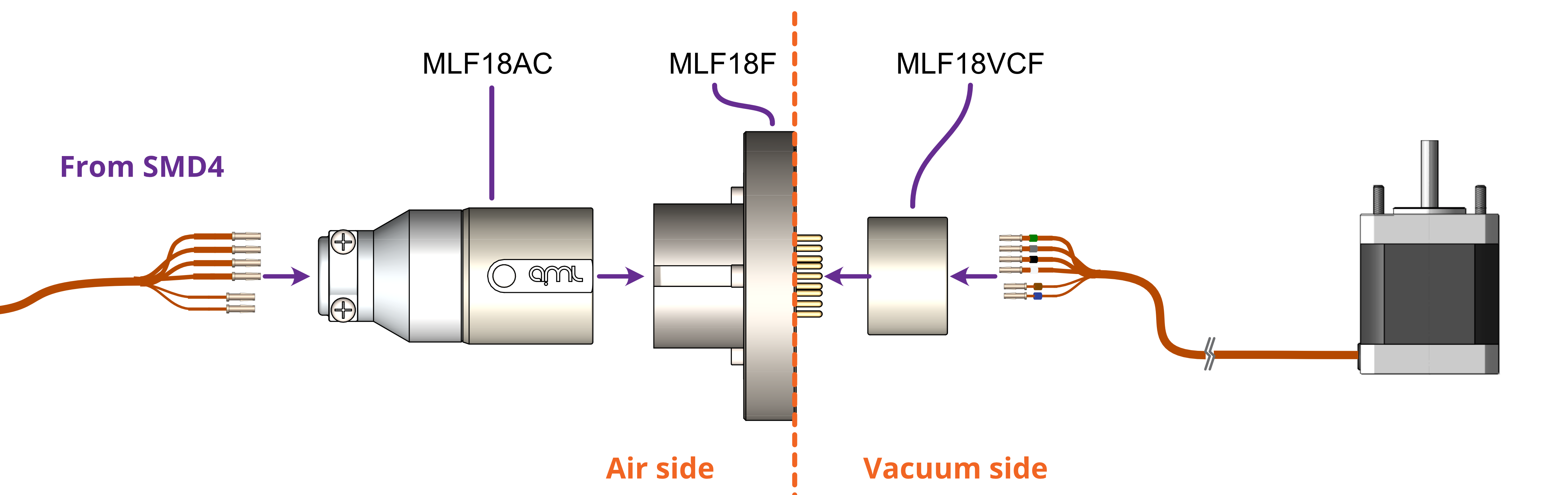
AML supply vacuum feedthroughs, ready-made cabling, and components allowing custom cables to be easily manufactured. A typical setup is shown below and used for illustration throughout this section.
INFORMATION: Verify that the motor is working correctly before sealing the vacuum chamber. Rectifying mistakes afterwards is inconvenient.
Lead identification
The motor leadout wires are self-coloured polyimide film-wrapped, silver-plated OFHC solid copper and each is fitted with a 1.5 mm crimp socket terminal. They are supplied fitted with UHV compatible coloured glass beads for identification. The phase leadout wires are much thicker than the thermocouple leadouts. The leadout wires of each phase should be twisted together.
 |
|
If the identification beads have been removed, the wires can be identified using an inexpensive multimeter, and a magnet. The multimeter must be capable of measuring resistance with a resolution of about 1 ohm.
|
|
|||||||||
|
|
||||||||||||
Phase leadouts
These are the four thicker leadouts. Identify the two motor phases by their resistance, which will be in the range of 3 to 15 ohms, depending on the motor type. There is no electrical connection between the two phases, to the thermocouple/RTD or the case of the motor. Most of the resistance is in the windings of the motor and is virtually unaffected by shortening of the leads. Connect each phase to the appropriate drive terminals. The resistance of the wires from the feedthrough to the drive must be less than a few ohms.
Note regarding reversal of rotation
Upon completion of wiring, there is a 50 % probability that the direction of rotation will be reversed from the desired or conventional sense. To rectify this, exchange the connections to one of the phases. For example, locate the Phase A + and Phase A – connections, and swap them around. This can be done on air or vacuum side while the chamber is still open.
Wiring motor to a vacuum feedthrough
AML motors are commonly connected via an MLF18 feedthrough or a standard D-Sub feedthrough.
9-Way D-Sub
The VC9D-40CF 9-way D-Sub male feedthrough is suitable for one motor fitted with either a thermocouple or 3-wire RTD. The standard crimp terminals supplied with AML motor leadout wires should be removed and replaced with a VC9DF PEEK D-Sub female connector and crimp terminals. An optional VC9DB cable strain relief is also available.
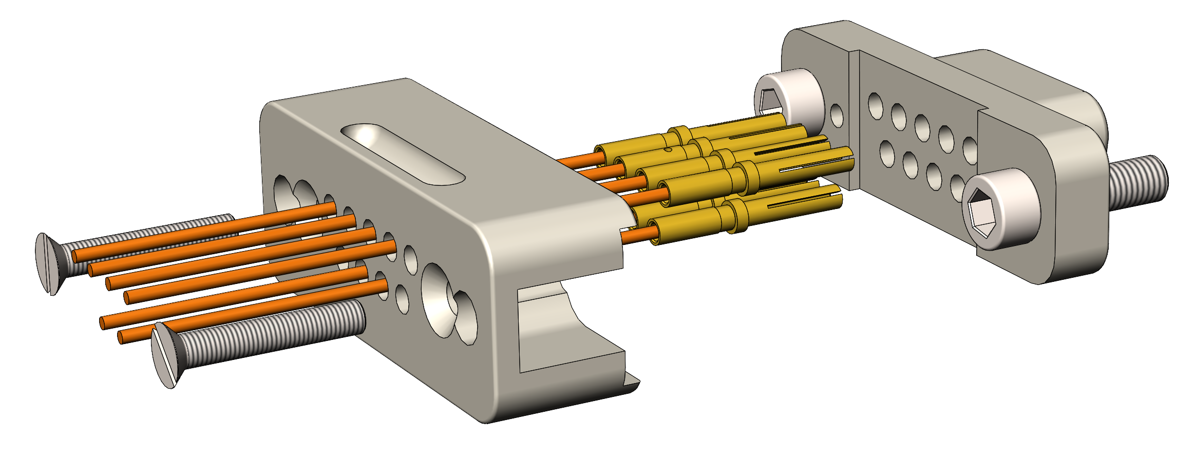
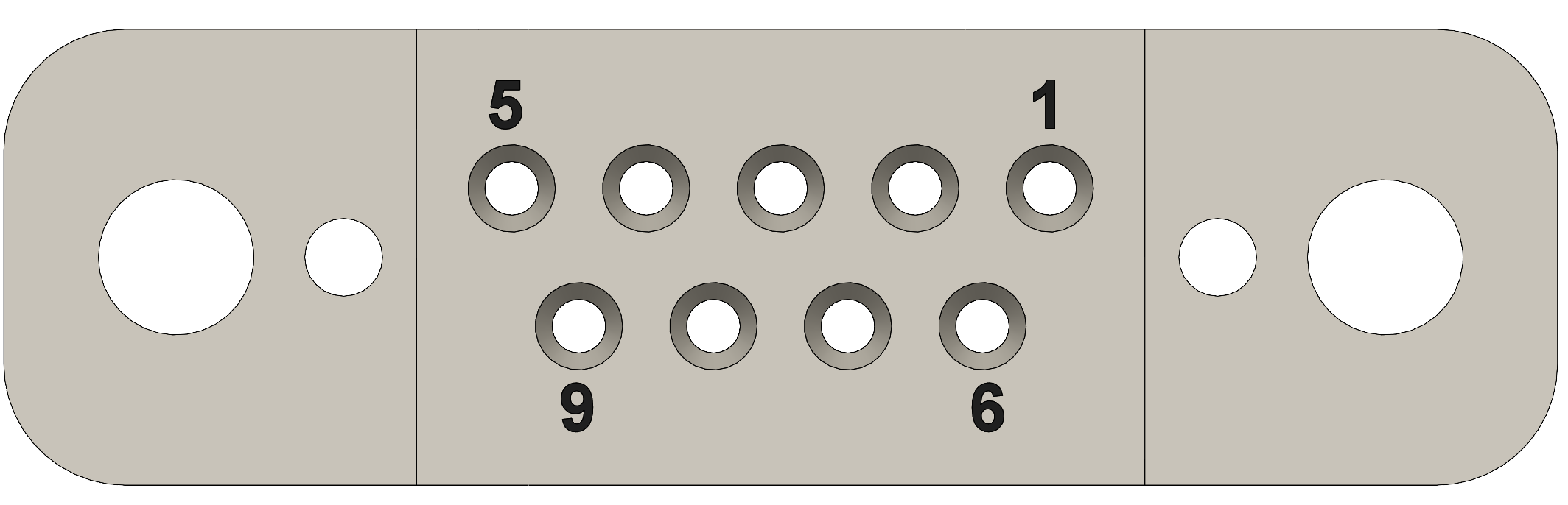
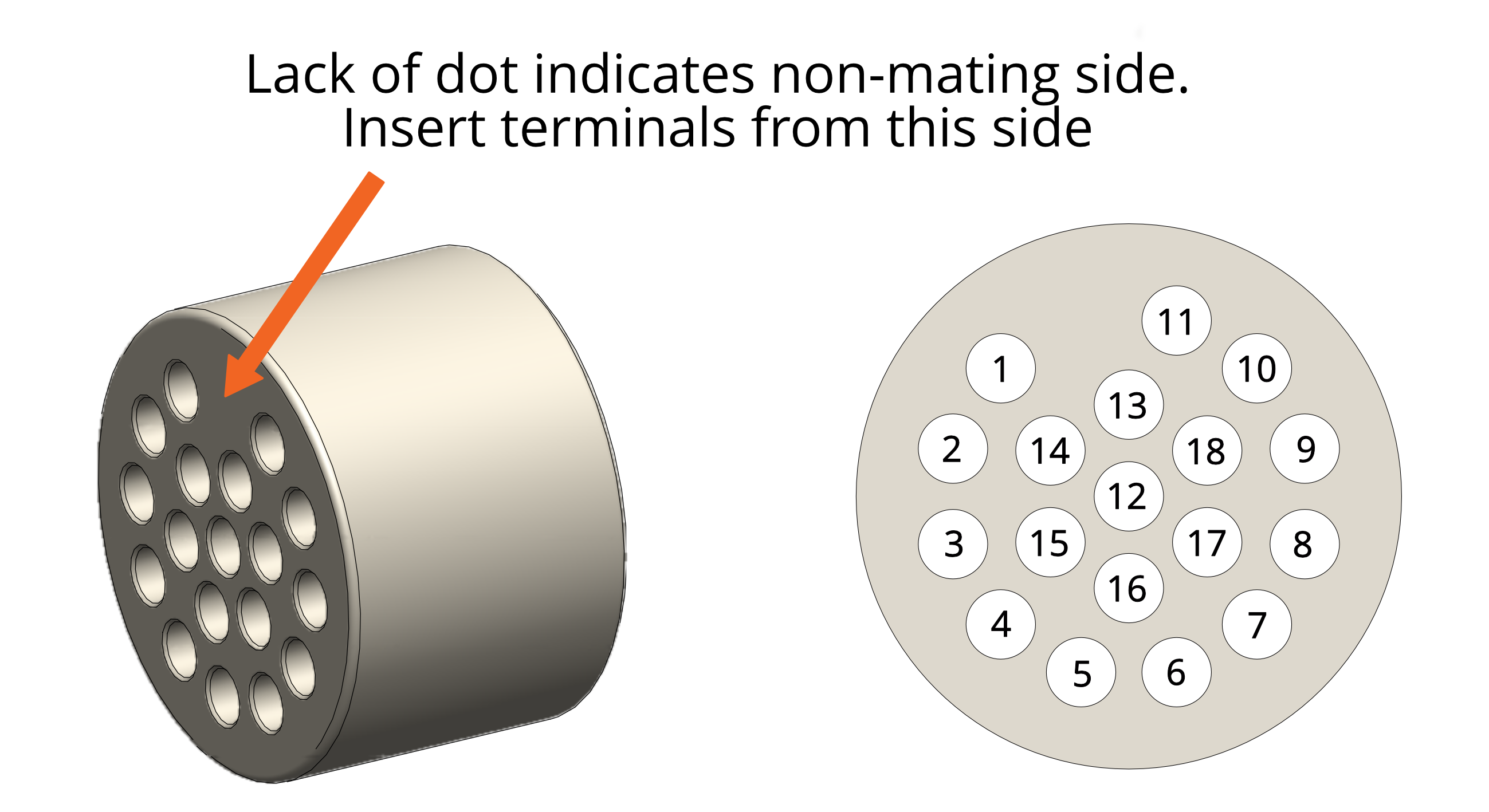
Motor wires pinout for the VC9DF
The illustration below shows the view into the non-mating side of the connector, into which the motor leads should be inserted, as shown below. Pass the wires through the backshell before crimping.
| Connection | Colour | Pin |
| Phase A1 | Green | 4 |
| Phase A2 | Grey | 3 |
| Phase B1 | Black | 2 |
| Phase B2 | White | 1 |
| Thermocouple + | Brown | 8 |
| Thermocouple - | Blue | 7 |
| RTD A | Blue | 5 |
| RTD B1 | Brown | 6 |
| RTD B2 | Brown | 9 |
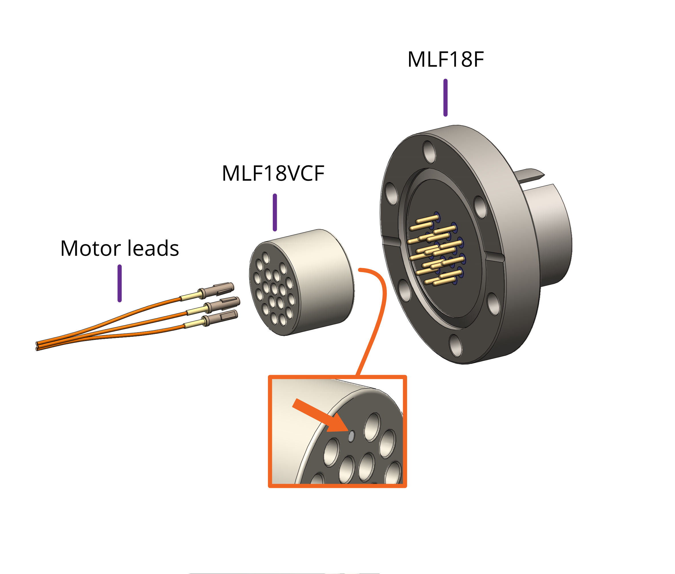
18-Way MLF18
The MLF18F feedthrough has 18 x 1.5 mm gold-plated feedthrough pins and is suitable for up to three motors fitted with thermocouples or up to two motors fitted with 3-wire RTDs. An internal bakeable connector, MLF18VCF, is available into which the crimp terminals on the motor leads are inserted. This significantly reduces the risk of short-circuits and makes the installation more convenient.
|
Using other feedthroughs
AML stepper motors can be ordered with either a K-Type thermocouple, or 3-wire PT100 RTD. The former requires 6 pins, and the latter 7 pins.
When using motors installed with a thermocouple, it is not necessary to use a thermocouple vacuum feedthrough or extension wires, as the error introduced by incompatible feedthrough material is usually less than 5 °C and the temperature measurement is not required to be very precise.
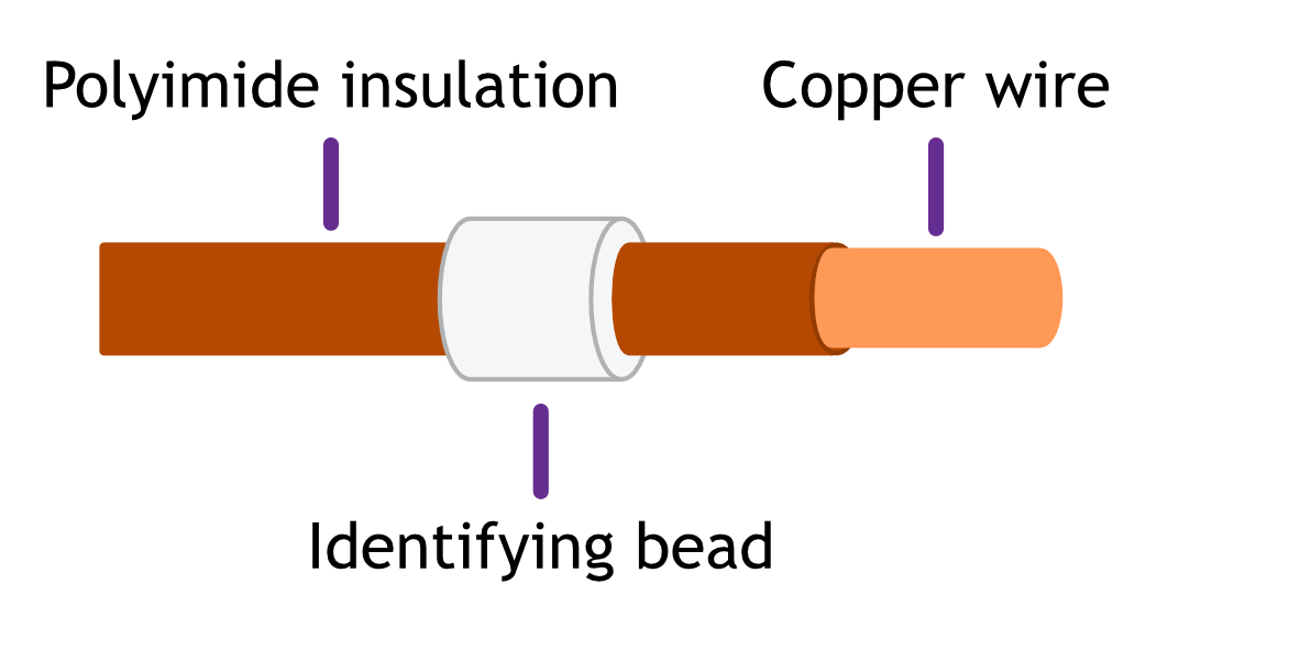
Preparation of Motor Leadout Wires for use with Other Feedthroughs
It will be necessary to cut off the crimp terminals fitted to the leads and re-strip them. Standard motors are fitted with Polyimide film-wrapped leads: radiation-hard motors are fitted with Polyimide lacquer-coated leads.
Polyimide is strong, flexible and abrasion-resistant and therefore difficult to strip. The simplest method of stripping polyimide film is to cut a ring with a sharp knife and withdraw the cylinder of insulation over the end of the wire. Be careful not to mark the conductor surface with the knife. Strip lacquer-coated radiation-hard leads by scraping with a sharp knife.Either type of lead may be stripped with a suitable high-speed rotary stripper. Do not use a thermal stripper.
Reversal of Rotation
There is a 50% probability that the direction of rotation will be reversed from the desired or conventional sense. To reverse the direction, exchange the connections to one of the phases.
Check that the drive, wiring and motor combination work properly before closing the vacuum system.
Troubleshooting
If the motor rotates at the wrong speed, frequently changes direction, or has low torque this is probably due to one of the phase connections being open circuit.
If the drive indicates that the motor temperature exceeds 190 °C when the motor is not hot, then a connection to the thermocouple is open circuit
General Operation Considerations for UHV-Compatible Motors
It is recommended that motors and mechanisms are operated in air during early commissioning. This has the advantage that more cooling is available and that the operator can see and hear that the motor is stepping.
-
Temperature Rise and Run Times
The maximum recommended operating temperature of AML motors is 190 °C, as measured by the embedded type K
thermocouple.
The motor should be run at the minimum phase current consistent with the requirements of the load. This will reduce the
maximum temperature of the motor and outgassing from the motor. Resistive heating losses in the winding resistance, R, are
given by I2R. The winding resistance is approximately proportional to absolute temperature so even small reductions in phase current, I, produce worthwhile reductions in temperature rise and outgassing. For phase currents down to about 50% of maximum the output torque is reduced roughly in proportion to phase current.
The minimum practical phase current is determined by the load friction and inertia, and the required acceleration and
maximum speed. It is best found by experiment. A reasonable margin of safety should be allowed for any expected increase
in load friction, which might occur after bakeout.
Vacuum stepper motors achieve maximum efficiency at full-step rates between 500 Hz and 2 kHz.
The SMD3 allows the reduction of the phase current dynamically during each step at low step rates, with separate control of
initial and final currents and transition times. Use of this technique can dramatically reduce the power dissipated in some
applications. The provision of heatsinking will improve the performance.
Irreversible deterioration of the winding insulation will occur at 230 °C and the motor will subsequently produce large amounts of gas, even at lower temperatures. -
Outgassing and Bakeout
A newly installed motor will outgas in vacuum, mainly due to water-vapour retention in the polyimide. As this material is microporous the water is released rapidly and the rate will subside after a few hours. The rate may be accelerated by running the motor to self-heat it.
Baking at up to 200 °C is required for operation at UHV. Motors are typically operated at some distance from the chamber
walls where the bakeout temperature is most often controlled. The motors will not reach a high enough temperature in such
cases, and it may be increased by using the windings as heating elements. The SMD3 includes a bake program, which
automatically controls the motor temperature at 200 °C by applying phase current. Maintain the motor temperature above
that of the rest of the system during cooling, as this will prevent condensation on the motor. Where internal infra-red heaters
are used for bakeout it is advisable to shield the motor from direct radiation and to achieve controlled temperature during
bakeout solely by self-heating.
The outgassing rate for well-baked motors installed on a typical mechanism and run below 120 °C winding temperature is in
the order of 10-8 millibar litres sec-1. This represents high duty-cycle operation at rated phase current for size 35, 42 & 57
motors. The gas species are H2 (90%) and CO (10%) and originate mainly from the windings and laminations. As a rule of
thumb, an additional 100 litres per second of pumping capacity per motor will be required for UHV. This gas load is insignificant at HV and higher pressures. -
Rotating Mechanisms – Holding Torque
Design rotation mechanisms with balanced loads to reduce or eliminate the necessity for holding torque. If the torque imposed on the motor by any imbalance of the load is less than the detent torque, then the motor will hold position without power. The gearing required to achieve the desired angular resolution or to match the load inertia will increase the effect of detent torque and also add friction. -
Translation Mechanisms – Shaft End-Float
The motor shaft has a compression spring, which pushes the shaft toward the mounting-face of the motor. The amount of
end-float is 100 to 200 µm for D35.1 and 200 to 400 µm for D42 motors. The spring is fully exercised with an axial force of 3 kg toward the rear of the motor. For linear mechanisms where the motor is directly coupled to a leadscrew use gravity and/or
apply an opposite axial pre-load to avoid adding end-float to backlash.
There may be a significant static friction component added to the compression spring force, which may give the impression
that the end-float is less or that the spring is stiffer than specified. This should not be relied on to reduce backlash, as
repeatedly exercising the end-float will reduce the static friction and may also produce particles. -
Resonances
Stepper motors are classic second-order systems and have one or more natural resonant frequencies. Operation at step rates
around these frequencies will excite the resonances, resulting in very low output torques and erratic stepping. The resonant
frequency is modified by the friction and inertia of the load, the temperature of the motor and by the characteristics of the
drive and therefore cannot be stated with any precision. Fortunately, coupling a load normally reduces the resonant
frequencies, which for unloaded AML motors occur below 300 Hz. The drive circuits of the SMD3 are optimised to produce
heavy damping of mechanical oscillations in the motors.
The simplest method of controlling resonances is to avoid operation of the motor close to the resonant frequencies. It is almost always possible to start a motor at rates in excess of 400 Hz if the load inertia is matched as described in the next section. Resonances are not usually a problem when the motor speed is accelerating or retarding through the resonance frequency region.
If it is necessary to operate at slower speeds than this, the step division feature (micro-stepping) helps by effectively increasing the stepping rate by the step division factor and reducing the amplitude of the step transients which excite the resonances. In particularly difficult cases modifying the step frequencies at which transitions to micro-stepping occurs can be useful. -
Load Inertia and Reduction Gearing
The load inertia coupled to the motor shaft should ideally be comparable to the rotor inertia of the motor where accurate
position control is required. The load inertia can be very much larger for speed control applications where some slip of
absolute position is unimportant. Where reduction gearing is used for load-matching the spur gear meshing with the motor
pinion will normally dominate the load inertia and it is important to keep its diameter small. Loosely coupled loads may give
rise to additional resonances at higher frequencies: these can usually be damped by substituting either anti-backlash or helical gears in the gear train or arranging additional friction in the train. -
Magnetic Fields Near the Motor
It is recommended that motors are not operated in fields of greater than 50 millitesla (500 gauss), as this will affect the
performance while the field is present. Fields significantly greater than this may cause partial demagnetisation of the rotor,
permanently affecting the performance.
The leakage field of a motor is less than 100 microtesla (1 gauss) at 1 cm from the surface of the motor and in an axial direction. It is due to the permanent magnet in the rotor and is present when the motor is stationary and unpowered. Under drive an alternating component is added at the fundamental and harmonics of step frequency, up to a few kHz. This field is easy to screen at the sides and non-shaft end of the motor, but more difficult at the shaft end because of the projection of the shaft. Early consideration of the interaction of stray fields on nearby equipment is recommended