SMD3 User Manual
UHV Stepper Motor Drive
- Introduction
- Technical information
- Installation
- Operation
- Software
- USB interface
- Guidance on use of VCSMs
- Maintenance and service
- Compliance Certificate
Introduction

The SMD3 stepper motor drive is a single-axis bipolar stepper motor drive, intended for use with AMLs range of vacuum compatible stepper motors (VCSMs), with maximum performance and minimal heat.
Powerful software is supplied with the SMD3 that enables you to control and configure multiple SMD3 units simultaneously, in a single, user-friendly graphical interface.
Liability and warranty
AML assumes no liability and the warranty becomes null and void if the end-user or third parties:
- Disregard the information in this document
- Use the product in a non-conforming manner
- Make any kind of alterations (modifications, repair work, etc.) to the product
- Use the product with accessories not listed in the corresponding product documentation
We reserve the right to make technical changes without prior notice. The figures are non-committal.
Safety and warning notices
WARNING! All work described in this document may only be carried out by persons who have suitable technical training and the necessary experience or who have been instructed by the end-user of the product.
The safety of any system incorporating the instrument is the responsibility of the assembler of the system.
Use the instrument only as specified in this manual, or the protection provided by the instrument might be impaired.
Ignoring this or subsequent safety information could lead to personal injury, or malfunction or permanent damage to the equipment.
Technical information
General
| General |
|
| Interface | USB Type-C (appears as virtual COM port on PC |
| Dimensions | 180 mm x 105 mm x 26 mm |
| Weight | 0.6 kg |
| Protection class | IP 20 |
| Temperatures |
Operation 10 °C to 60 °C, Storage -10 °C to 85 °C |
| Power supply | External 15 Vdc to 67 Vdc power supply required |
| Power consumption | 28 W maximum |
| Motor | |
| Suitable types | 2 phase bipolar stepper motor with 4 leads |
| Phase current | Up to 1 A RMS, adjustable in 30 mA steps |
| Source voltage | As supply voltage, 67 Vdc maximum |
| Resolution | 8, 16, 32, 64, 128, 256 micro-stepping |
| Protection | Short to ground and phase to phase |
| Operating modes |
|
|
|
| Limits |
|
| Quantity | 2 |
| Compatible switch types | Mechanical NO or NC (polarity selectable) |
| Protection | Withstands continuous short to 12 V maximum |
| Miscellaneous | Source current < 1 mA |
| Motor temperature measurement |
|
| Type | Selectable PT100 RTD or K-Type thermocouple |
| Range | -200 °C to 240 °C |
| Accuracy | ±5 % |
| Fault detection |
RTD: Open and short-circuit Thermocouple: Open circuit only |
| SDE (step, direction, enable) interface |
|
| Type | Optocoupled, bi-directional LED |
| Levels | 3.3 Vdc to 5 Vdc maximum |
| Maximum frequency | 2 MHz at 50 % duty |
| Joystick |
|
| Connection | Front panel mounted 4P4C jack |
| Input type | Active low, short to ground to activate function |
| Miscellaneous | Open circuit voltage 3.3 V, source current < 3.5 mA |
| Software |
|
| Compatibility | Windows 7 or later |
Mechanical
All dimensions are in millimetres.

Scope of delivery
|
Qty. |
Item |
|
1 |
SMD3 |
|
1 |
USB Type-A to USB Type-C lead |
|
1 |
Pluggable terminal block, 2-way, 3.5 mm pitch |
|
1 |
Pluggable terminal block, 5-way, 3.5 mm pitch |
|
1 |
Pluggable terminal block, 12-way, 3.5 mm pitch |
|
1 |
Type K Thermocouple Free Plug, Miniature |
Accessories
The following accessory items are available from AML.
|
Order Code |
Item |
|
SMD3JOY |
Joystick |
|
SPSU48V |
48 Vdc, 60 W Power Supply |
|
MLF18SMD3 |
Lead, Feedthrough to SMD3 |
Installation
Before installation
WARNING: Read this manual carefully before installing and operating the SMD3. Observe the following safety instructions.
Qualified personnel
WARNING: All work described in this document may only be carried out by persons who have suitable technical training and the necessary experience or who have been instructed by the end-user of the product.
WARNING: Without proper training and necessary experience, damage to the equipment or personal injury might result.
DANGER: Danger of electric arcing! Never plug or unplug any connector while powered. Plugging or unplugging a motor while powered may damage or destry the driver output stage
Additional safety and warning notices
Unpacking
On receipt of the instrument remove all packing material and check that all items on the delivery note have been received. Report any damage or shortages to the company or distributor who supplied the instrument. The packing material has been specially designed to protect the instrument and should be retained for possible future use.
Mechanical installation
The SMD3 may be mounted via the front panel and or underside flanges, in any orientation. Forced air ventilation is not required. The ambient operating temperature range is 10 °C to 60 °C.
Connecting
Rear panel
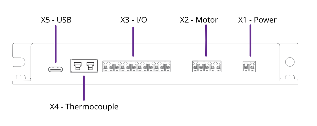
The Power, Motor and I/O sockets use 3.5 mm pitch pluggable rewireable terminal blocks. These are suitable for 28 – 16 AWG (1.5 mm2 max.) stranded wire. Strip insulation to approx. 6 – 7 mm before securing the wire in the terminal block.
Connectors are supplied for X1, X2, X3 and X4. Replacement connectors are available from IMO Precision Controls, part number 20.1550M/X-E where ‘X’ is the number of ways. For example, the part number for the power connector pluggable terminal block would be 20.1550M/2-E. These are readily available from electronics distributors.
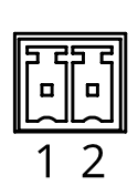
X1 - Power
|
|
1 | GND |
| 2 |
V+ |
Power input for both internal logic circuits and the motor itself.
The power supply must meet the following requirements:
- 15 – 67 V DC regulated supply, 30 W minimum
- Reinforced or double insulation between mains and supply output
DANGER: Danger of electric arcing! Never plug or unplug the connector while powered.
CAUTION: In the event of reverse polarity, a short circuit will occur between GND and V+ through an internal power diode. Therefore, an external fuse must be installed in the supply line.
The fuse should be sized:
- Greater than the current consumption of the SMD3 when operating the connected motor
- Less than the maximum current output of the power supply
- Considering the voltage of the supply
INFORMATION: Choice of input voltage affects motor performance; operating at the maximum voltage possible (67 Vdc) will maximise motor torque at higher speeds.
X2 - Motor
|
|
1 | GND |
| 2 | Phase A1 | |
| 3 | Phase A2 | |
| 4 | Phase B1 | |
| 5 | Phase B2 |
Motor output. Connection of the motor to the vacuum feedthrough, and vacuum feedthrough to the SMD3 is discussed in section Motor Wiring.
Custom motor cables must be built to the following specification to ensure continued compliance with EMC standards and correct function:
-
Four cores, comprising two twisted pairs plus screen. A foil screen plus drain wire is acceptable; a foil plus braid screen is better
-
The screen must be connected via as short a wire as possible to pin 1, ‘GND’, using insulated wire
-
Rated voltage >= 300 V rms
-
Rated current > 1.5 A rms
Maximum cable length is limited by the resistance of the cores; total round trip cable resistance per phase should be kept to less than few ohms. Consult the cable manufacturers data for these details.
DANGER! Danger of electric arcing! Never plug or unplug the connector while powered! Plugging or unplugging motor while powered may damage or destroy the driver output stages.
X3 - I/O
|
|
1 | GND |
| 2 | RTD B2 | |
| 3 | RTD B1 | |
| 4 | RTD A | |
| 5 | LIMIT 1 / Positive | |
| 6 | LIMIT 2 / Negative | |
| 7 | FAULT | |
| 8 | RESET | |
| 9 | SDE COM | |
| 10 | STEP | |
| 11 | DIR | |
| 12 | EN |
X4 - Thermocouple
|
|
- | T/C - |
| + | T/C + | |
The connection is for use with a standard IEC Miniature K-Type thermocouple plug. These are colour coded green for K-Type thermocouples.
X5 - USB
|
|
||
USB Type-C connection. The connection is reversible, and the plug may be inserted either way up.
The SMD3 appears as a virtual COM port when connected to the PC. No additional drivers are required. Configure and control the SMD3 using the supplied SMD3 software, a terminal program, or your own application. AML supply a C# API, available on our website to help customers implement their own applications faster.
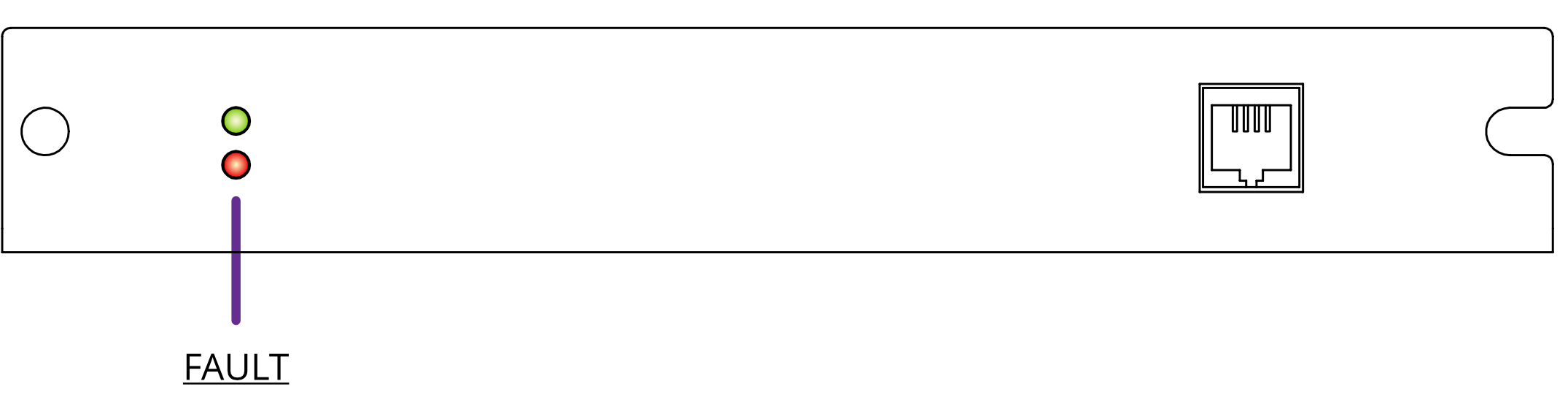
Front panel
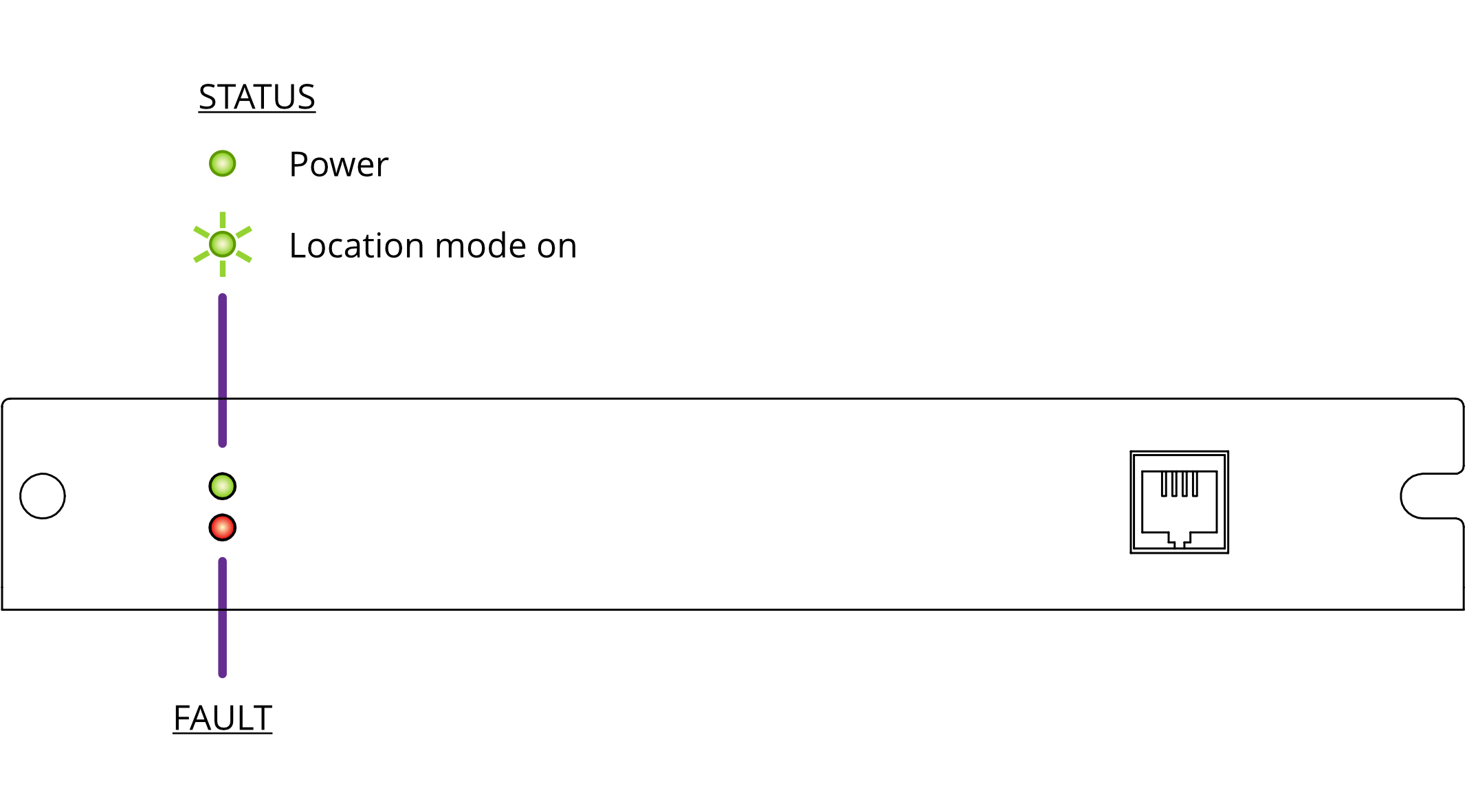
The fault indicator flashes or remains lit if the SMD3 is in a fault state (see section Faults for fault indications). When a fault is present, motor operation is disabled.
X6 - Joystick
|
|
1 | GND |
| 2 | CW | |
| 3 | CCW | |
| 4 | DETECT |
For connection of a two-button joystick allowing basic motor control, for example, during commissioning. AML supply the SMD3 Joystick, part number ‘SMD3JOY’ for this purpose. On connection, the SMD3 automatically switches to joystick mode.
- If designing your own joystick or device to connect to this port:
- Inputs have internal pull-ups.
- Activate the function by shorting ‘CW’, ‘CCW’ or ‘DETECT’ to pin 1, ‘GND’.
- Pin 4, ‘DETECT’ is used to signal to the SMD3 that the joystick is connected and trigger automatic switch to joystick mode. If not required, leave the pin unconnected. This requires joystick mode to be manually selected.
Logic level signals may also be used; 12 V max.
Motor wiring
Overview
Connecting motors inside a vacuum chamber to the SMD3 comprises two tasks:
-
Wiring the motor to a vacuum feedthrough installed in the chamber wall.
-
Wiring the vacuum feedthrough to the SMD3.
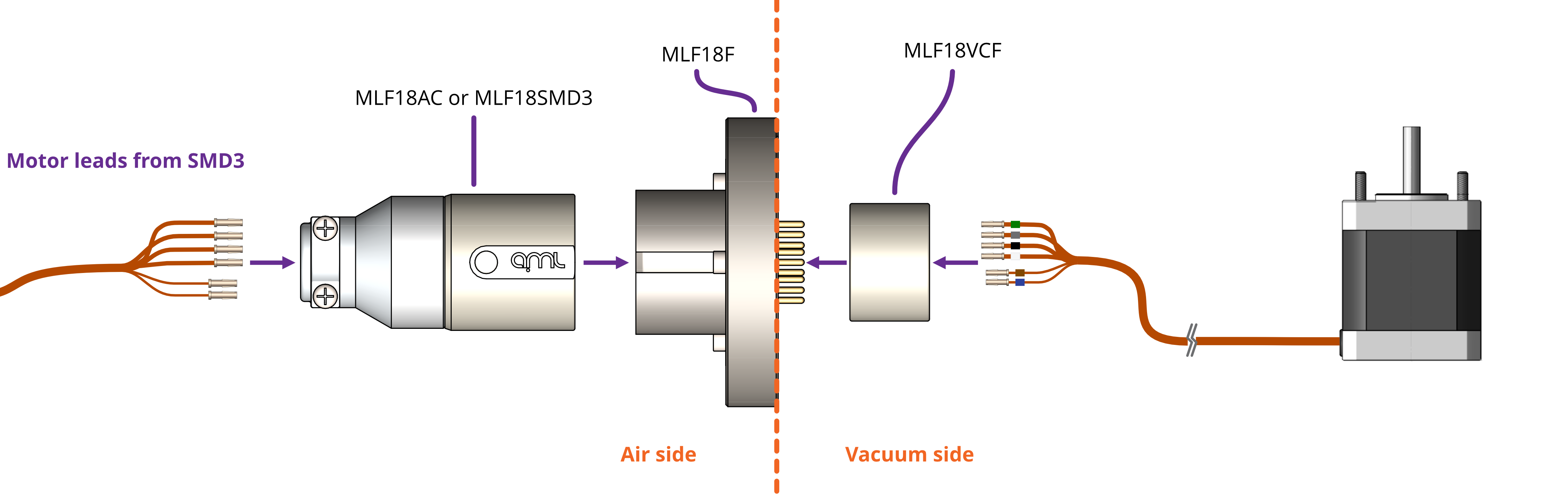
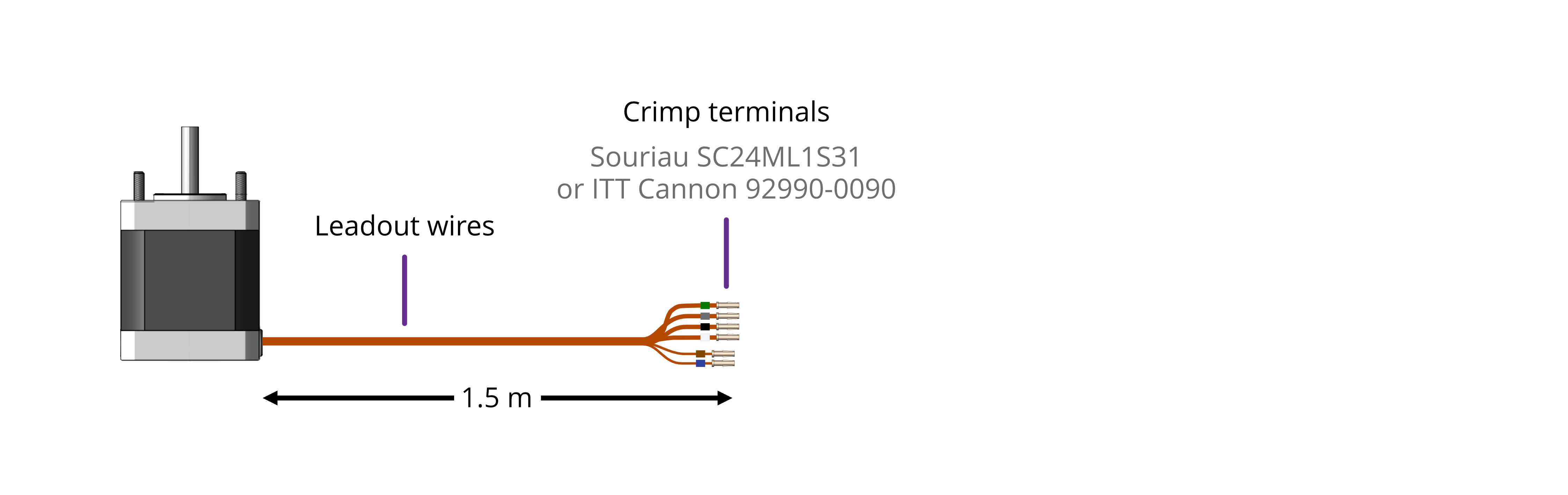
AML supply vacuum feedthroughs, ready-made cabling, and components allowing custom cables to be easily manufactured. A typical setup is shown below and used for illustration throughout this section.
INFORMATION: Verify that the motor is working correctly before sealing the vacuum chamber. Rectifying mistakes afterwards is inconvenient.
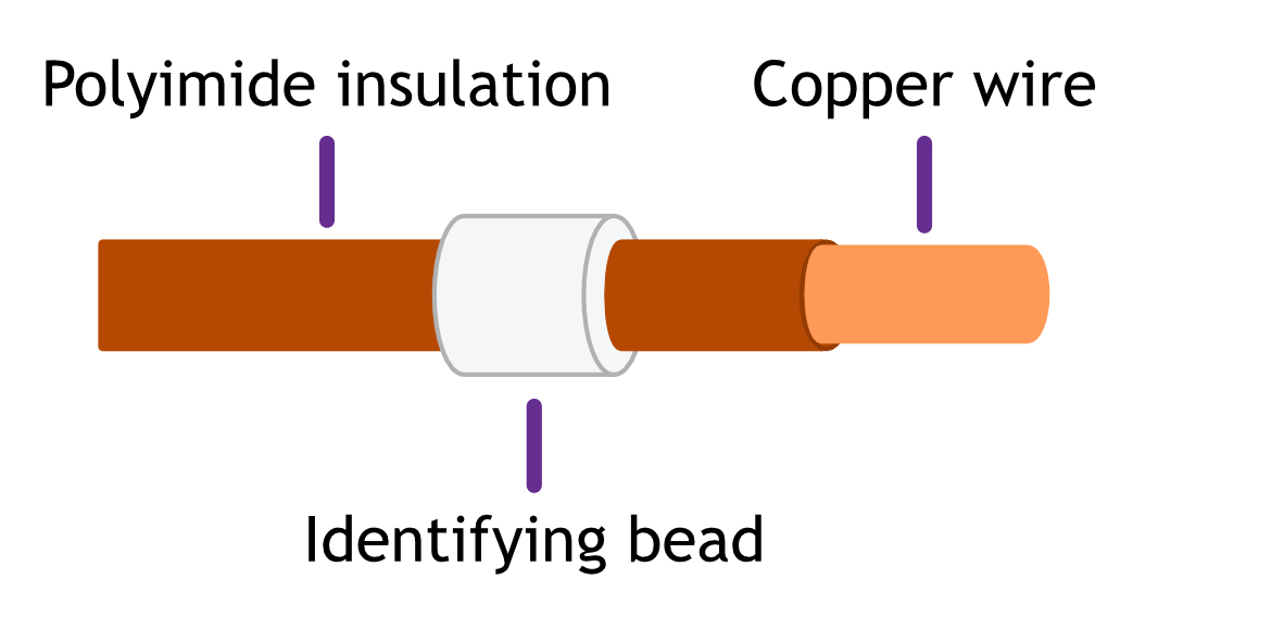
Lead identification
The motor leadout wires are self-coloured polyimide film-wrapped, silver-plated OFHC solid copper and each is fitted with a 1.5 mm crimp socket terminal. They are supplied fitted with UHV compatible coloured glass beads for identification. The phase leadout wires are much thicker than the thermocouple leadouts. The leadout wires of each phase should be twisted together.
 |
|
If the identification beads have been removed, the wires can be identified using an inexpensive multimeter, and a magnet. The multimeter must be capable of measuring resistance with a resolution of about 1 ohm.
|
|
|||||||||
|
|
||||||||||||
Phase leadouts
These are the four thicker leadouts. Identify the two motor phases by their resistance, which will be in the range of 3 to 15 ohms, depending on the motor type. There is no electrical connection between the two phases, to the thermocouple/RTD or the case of the motor. Most of the resistance is in the windings of the motor and is virtually unaffected by shortening of the leads. Connect each phase to the appropriate drive terminals. The resistance of the wires from the feedthrough to the drive must be less than a few ohms.
Note regarding reversal of rotation
Upon completion of wiring, there is a 50 % probability that the direction of rotation will be reversed from the desired or conventional sense. To rectify this, exchange the connections to one of the phases. For example, locate the Phase A + and Phase A – connections, and swap them around. This can be done on air or vacuum side while the chamber is still open.
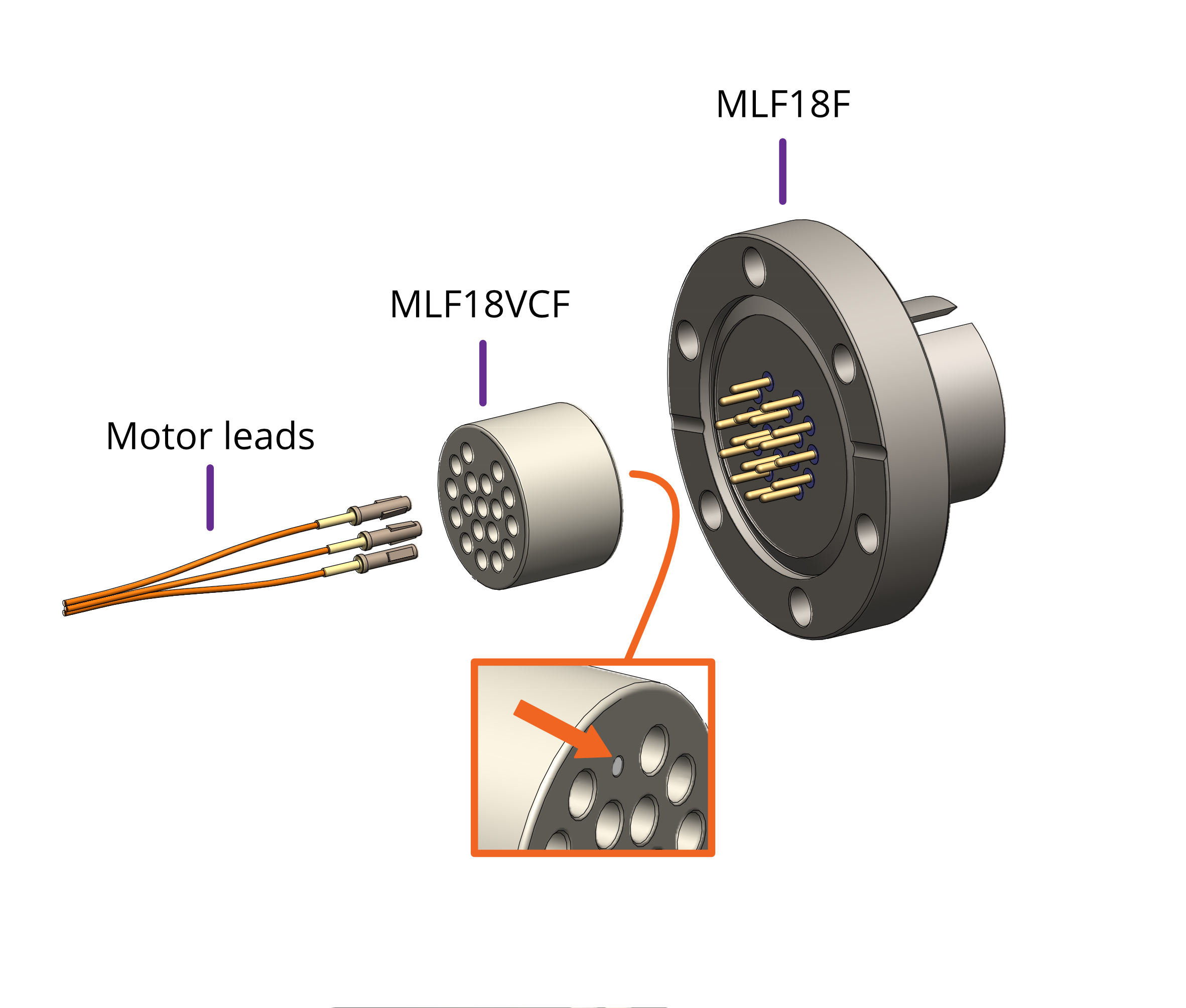
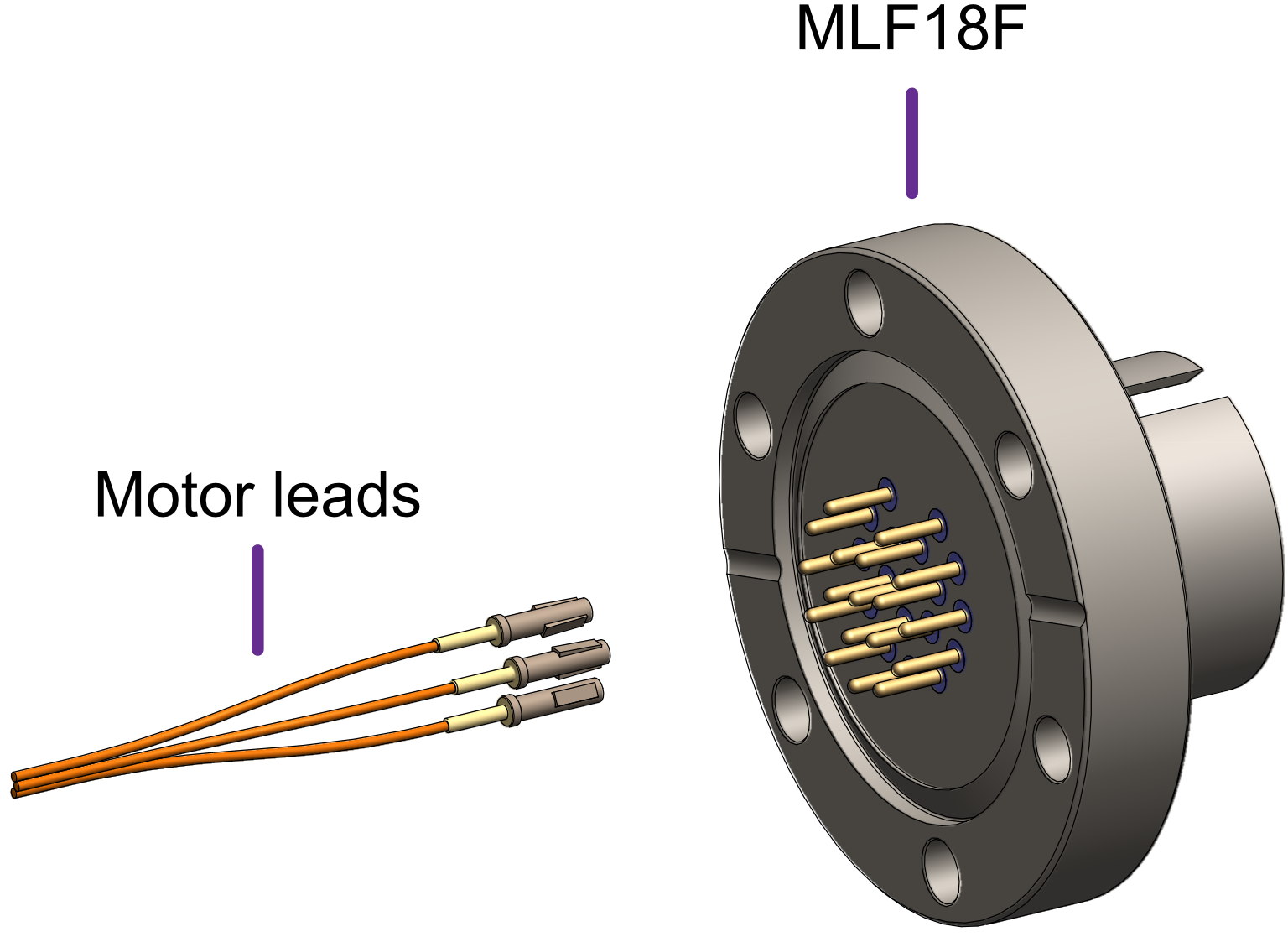
Wiring motor to the vacuum feedthrough
The MLF18F feedthrough has 18 x 1.5 mm gold-plated feedthrough pins and is suitable for up to three motors fitted with thermocouples or up to two motors fitted with 3-wire RTDs. An internal bakeable connector, MLF18VCF, is available into which the crimp terminals on the motor leads are inserted. This significantly reduces the risk of short-circuits and makes the installation more convenient.
|
Using other feedthroughs
AML stepper motors can be ordered with either a K-Type thermocouple, or 3-wire PT100 RTD. The former requires 6 pins, and the latter 7 pins.
When using motors installed with a thermocouple, it is not necessary to use a thermocouple vacuum feedthrough or extension wires, as the error introduced by incompatible feedthrough material is usually less than 5 °C and the temperature measurement is not required to be very precise.
Wiring between drive and vacuum feedthrough
AML supply the MLF18SMD3 lead for use with the SMD3 and MLF18F feedthrough. It allows connection of up to two drives and motors installed in one vacuum chamber. Alternatively, AML supply the MLF18AC; which can be used to make custom leads to mate with the MLF18F feedthrough. This is supplied with a kit that includes the crimps and a grounding lead attached to the connector shell, as well as instructions for their use. The SMD3 is supplied with a kit of matching connectors.
Leads between the MLF18AC and SMD3 should be assembled according to the following guidance for safe, reliable operation and continued compliance with EMC standards.
Cable requirements
- Quantity of cores as required; (one motor requires 6 cores when fitted with a thermocouple, or 7 if fitted with an RTD). The cable must be screened. A foil screen plus drain wire is acceptable; a foil plus braid screen is better.
- The screen must be connected via as short a wire as possible to pin 1, ‘GND’ of the motor connector, using insulated wire.
- Rated voltage >= 300 V rms
- Rated current > 1.5 A rms
- Cable cores must be twisted together in pairs, using one pair per phase, one pair for the thermocouple, and a group of three for the RTD. This reduces radiated emissions from the cable and improves immunity of the RTD and thermocouple signals to the motor.
- Maximum cable length is limited by round trip resistance, which should be less than a few ohms. Review cable manufacturers data to obtain this figure.
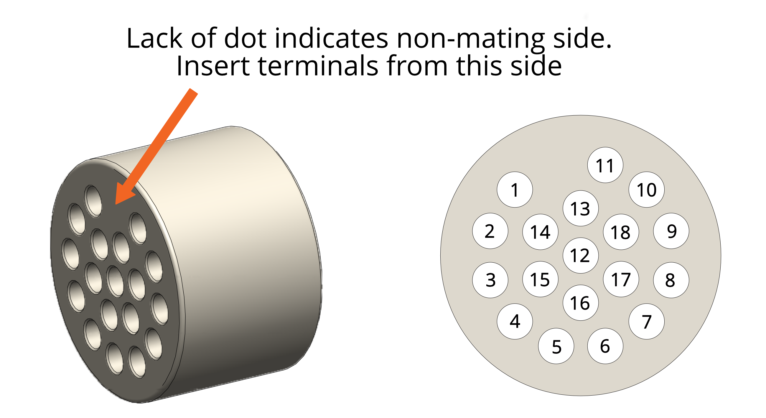
Wiring up to the MLF18AC airside connector
The MLF18AC is supplied with comprehensive instructions detailing correct usage of the connector. The pinout to match with the standard MLF18F + MLF18VCF pinning described in section Motor wiring is shown below. Note that the illustration shows the MLF18AC looking into the non-mating side of the connector, i.e. the side into which crimps are inserted.
|
||||||||||||||||||||||||||||||||||||||||
Operation
Getting started
The quickest way to get started with the SMD3, having completed wiring up according to the previous chapter is to install the SMD3 software on your PC (see section Software), power on the SMD3 and connect it with the USB lead to the PC. The SMD3 software provides an intuitive and easy way to configure and evaluate the features of the SMD3 described in the remainder of this section.
This section discusses the various operational modes and configuration options available. The SMD3 software provides easy access to these functions, as well as help text describing each. If communicating with the SMD3 directly, using a terminal program or your own software, see section USB Interface which lists the commands available.
Operating modes
There are five operating modes:
|
Remote
Accepts commands from host PC or PLC; powerful software supplied, control and configure multiple axes at once. All setup (including mode selection) must be performed using the remote interface. |
Joystick
Ideal for basic movement during commissioning; press for one step, press and hold for continuous movement; latching mode option. |
|
Step/Direction
Opto-isolated step and direction; configurable rising or rising/falling edge; up to 256x interpolation. |
Bake
Heats the motor by energising both phases and holding the motor stationary, regulating the current to achieve a setpoint temperature. Used to drive off adsorbed moisture in the motor. |
|
Step/Direction triggered velocity
Start/stop using step signal, Positive/negative movement according to direction signal; configurable velocity profile. |
Home
Home mode drives the motor to the positive or negative limit switch. |


INFORMATION: Mode can be changed only when the motor is not performing any movement. This can be verified by checking the standby flag, which is returned in a status register by the SMD3 on every communication, see section USB Interface - Protocol. The firmware prevents mode change when the standby flag is not set.
In the case of Step/Direction mode, it is the responsibility of the external controller to perform any final activities, such as coming to a stop, before changing the mode.
Step/Direction
Motor movement is controlled by externally supplied step and direction signals. The SMD3 can be configured to step on the rising or rising and falling edges, which halves the step clock rate.
Note that the external enable fault is non-latching when in step direction mode; once the external enable state is restored, or the external enable setting is changed to false, normal operation will resume immediately without the need to clear it. See also section X3-I/O.
|
Step input |
|
Direction input |
|||
|
Both |
Rising only |
|
|
Meaning |
|
|
Rising |
Step |
Step |
|
Low |
Positive |
|
Falling |
Step |
|
|
High |
Negative |
Steps are generated according to the current resolution. For example, with the edge setting on rising only, and microstep resolution set to 128, each rising edge on the step input will generate a single 1/128th step in the positive direction.
A step interpolation option is available; when enabled, the step input behaves as it would with the current resolution, except that each step input is interpolated to 256 microsteps. This is done by evaluating the rate at which steps arrive and timing 256 microsteps within the step to step period. This gives all the benefits of microstepping at high resolution while minimising the input clock rate.
The relationship between step input, resolution and actual step frequency is given below:
Motor Step frequency [Hz] = (Step input [Hz] / Resolution)
INFORMATION: Stopping on fractional steps
There is no mechanism to prevent the motor from stopping on fractional steps as there is in all other modes.
Stopping on fractional steps will result in the motor temperature rising much faster than it otherwise would and is generally not suitable for vacuum applications. Therefore, configure the external step generator to meet this criteria.
INFORMATION: Preparation before switching out of Step/Direction mode
When changing to another mode from Step/Direction mode, ensure that any movement being commanded via Step/Direction interface has completed before switching.
Step/Direction triggered velocity
This mode works the same as joystick continuous mode, except that the positive and negative inputs that would normally be supplied via the joystick input are instead generated from the step and direction inputs:
|
Step input |
|
Direction input |
||
|
Meaning |
|
|
Meaning |
|
|
Rising |
Triggers start / stop |
|
Low |
Positive |
|
Falling |
No action |
|
High |
Negative |
Remote
Remote mode is used to perform all aspects of configuration and may also be used to control motor movement directly. The easiest way to do so is using the supplied SMD3 software, which allows one or more SMD3 units to be combined into a system and controlled individually or as a group. This makes it easy to apply the same configuration to multiple devices, for example.
Alternatively, the SMD3 may be controlled via a simple terminal application or your own software. The remote interface is described in section USB interface.
Joystick
Basic motor movements may be commanded via a two-button joystick connected to front panel connector, ‘X6–Joystick’. AML supply the SMD3 Joystick, part number ‘SMD3JOY’ for this purpose. On connection, the SMD3 automatically switches to joystick mode, and reverts to the previous mode on removal of the joystick. This behaviour can be disabled if required. Section X6-Joystick discusses the electrical aspects of the joystick input, including details for building a custom joystick.
There are two joystick modes; both operate using velocity mode (see section Velocity and Positioning Mode for details) in which a profile, including acceleration, deceleration and target frequency are programmed, then motor movement is triggered by the joystick.
|
Continous
|
Motor accelerates toward target frequency on joystick key down. Continuing to hold the key down has no further effect.
On releasing and pressing the same key again, the motor decelerates toward a stop.
On pressing the alternate direction key, motor first decelerates to a stop before accelerating toward target frequency in the other direction.
If the motor has not yet come to a stop, and the same key is pressed again, the motor will once more accelerate towards target frequency, as illustrated left. |

|
Single step
|
A short button press (< 0.5 s) causes a single step in the commanded direction. This is useful for precise positioning.
A long press (> 0.5 s) triggers acceleration toward the target frequency, while the button continues to be pressed.
Releasing the button causes the motor to decelerate toward a stop.
If the button is pressed while the motor is still decelerating, the motor once more accelerates toward target frequency for as long as the button is held. |

Bake
Bake mode regulates phase current to heat the motor to a specified setpoint temperature. The motor is held stationary. Before engaging bake mode, set the target bake temperature. When in bake mode, the green status indicator will flash briefly at intervals as a reminder that this mode is active.
Home
Home mode drives the motor to the positive or negative limit switch. The motor first moves toward the limit switch using the existing movement profile. On the limit switch being triggered, the step frequency is halved, and the motor reversed until the limit switch is not triggered. Finally, the motor moves toward the limit switch at a step frequency of 30 Hz until the limit switch is triggered.
INFORMATION: Limitations of limits
Limit switches are not latching, i.e. as soon as a limit input becomes not triggered, for example if the mechanism is able to first actuate a limit switch and then continue moving past it until the limit switch is no longer actuated, then the SMD3 will be unaware of this and will continue to drive the motor if commanded.
Limits switches and cams are normally arranged such that the limit switch is triggered from the desired point up to and including the point at which the mechanical limit of the mechanism is encountered.
General concepts
User interface
In general, all control and configuration of the SMD3 is performed via the remote interface. The following functions and indications are available locally on the SMD3:
- Basic status information, via front panel green and red indicators. Green signifies power on and normal operation, red a fault. See section Faults. The green indicator also blinks briefly when the operating mode is changed.
- Joystick control – plug a joystick into the front panel joystick connection, and basic movements may be performed according to the current configuration. See section Joystick.
- Step/Direction interface; if in this mode, the motor may be controlled via signals supplied on the I/O port. See section Step / Direction.
- Fault output and fault reset input on ‘X3 – I/O’ – An open collector fault output is set when a fault occurs. The fault state can be reset by pulling the fault reset pin to the ‘GND’ pin of ‘X3 – I/O’. See section Faults.
Persistence of settings
All changes made to the configuration via the remote interface are volatile (i.e. not retained on power cycling) unless the store command is executed before powering off. The AML SMD3 software warns you of this when closing the application, but if writing a custom application to control the SMD3, your application must handle this if settings are to be persisted.
The SMD3 will always load the last stored settings on power on, or if the store command has not been previously used, defaults are loaded as per section Command Reference. If settings become corrupted, for example the write endurance of the memory in which the settings are stored is exceeded, the SMD3 loads defaults as identified above, and a fault indication is given, see section Faults.
INFORMATION: Write endurance
The memory in which settings are stored has an endurance of about 1 Million write cycles. Only use the store command when necessary, for example, take care that your application does not perform multiple redundant store commands.
Motor current
Three values may be set for motor current; acceleration current, run current and hold current.
|
|
Applies when |
|
Acceleration |
Motor is running but not at target frequency, i.e. during acceleration and deceleration. This allows you to set a higher current during acceleration (to overcome inertia of a large load, for example) and revert to a lower current once the load is moving, thus reducing motor power dissipation and extending run time. If you do not wish to use this feature, simply set acceleration current to equal run current. |
|
Run |
Motor has reached target frequency. |
|
Hold |
Motor is stopped and is only necessary where the motor detent torque is not enough to prevent undesirable movement of the load. The cost of using hold current is increased motor temperature under vacuum. Therefore, where possible, mechanisms should be designed to be statically balanced, and the hold current should be set to 0. |
When the motor starts moving, acceleration current is applied immediately. When the motor stops after the deceleration, two additional states must be traversed before the acceleration current is reduced to hold current, first, a configurable delay during which acceleration current continues to be applied (called ‘standstill’ state), followed by a configurable delay during which acceleration current is reduced to hold current (called ‘going to standby’ state).
Run current must be set equal to or smaller than acceleration current. This is enforced by the SMD3; if a change to run current makes it greater than the acceleration current, the acceleration current is automatically adjusted to be equal to run current.
Standstill
Period after motor has stopped during which acceleration current is still applied. Adjustable between about 0 and 5.57 seconds using the ‘Power down delay’ setting [PDDEL]. Set to the minimum value suitable for your application to minimise heat generated.
Going to standby
Period during which acceleration current is gradually reduced to hold current. This smooth transition avoids a motor jerk on power down. Motor current is not continuously adjustable, instead being one of 31 discrete values from 0 to 1.044 A rms. Therefore, the current ramps down in steps. The step size may be set between 0 (instant power down) and 327 ms using the ‘Current reduction delay’ setting [IHD]. Set to the minimum value suitable for your application to minimise heat generated.
The name of each setting in the following illustrations matches that used in the software. The command mnemonic, for use if programming the SMD3 via the remote interface (see section USB Interface), is given in square brackets.
|
|

Figure 1 - Motor current and speed
Microstepping
Microstepping is applicable at low step frequencies (typically < 500 Hz) and helps reduce motor resonances resulting in smoother operation. In non-vacuum applications, it is also used to achieve increased positioning resolution, however, it requires energising both motor phases continuously even when the motor is stopped to maintain position, resulting in unacceptable levels of temperature rise in the motor in vacuum applications. Instead, mechanisms are designed to achieve the required positioning resolution with appropriate gearing.
Microstepping is not helpful at higher step rates, therefore, the SMD3 automatically switches between microstepping at low speeds and full step at high speeds. The transition point from full step to microstep is configurable, as illustrated in Figure 1. Hysteresis is applied to this value resulting in the transition in the opposite direction (from microstep to full step) being at a slightly higher frequency, as illustrated above. Note that you cannot explicitly set the transition to full step point, only the transition from full step to microstep. The other transition is calculated automatically.
The resolution to use during microstepping is configurable, via the microstep resolution setting [RES]. Choices are 8, 16, 32, 64, 128 and 256. In all modes except for step/direction, the motor is only stopped in full-step positions. Microstepping is used exclusively for the purpose of smoothing the transition between steps.
The accuracy with which motor profile (acceleration, deceleration, etc.) settings may be made depends on the microstepping resolution; the maximum microstep resolution of 256 offers the greatest accuracy for these settings.
Freewheel mode
Freewheel mode refers to how the motor is configured when it is at standstill and zero hold current is set. There are three choices:
-
Use freewheel for minimum holding torque, which allows the motor shaft to be moved freely.
-
Phases shorted for maximum holding torque with zero power applied to the motor (and so no heat generated in the motor).
-
Normal offers some minimal amount of holding torque as a result of the phases still being connected to the driver circuitry.
Velocity and Positioning mode
All modes except step/direction fundamentally use the hardware of the SMD3 in one of two ways:
- Velocity mode. Motor is accelerated to a target velocity in a specified direction (Positive or Negative), which may be maintained indefinitely. On stopping, the SMD3 decelerates according to the configured profile and stops in a full step position.
- Positioning mode. Motor is driven toward a chosen position, determined by an internal step counter and a relative or absolute step count position. The motor starts by accelerating towards the target velocity, then as the target position is approached begins to decelerate before coming to a stop at the target position. Position can be specified in full steps only.
Step/direction triggered velocity mode uses velocity mode internally and joystick mode uses a combination of velocity and positioning mode. In remote mode, velocity and positioning mode must be selected with the appropriate command.
Initiating movement
In remote mode, movement is started via a run command and stopped via stop command. Movement cannot begin spontaneously as a result of changing a setting, for example. Direction is specified as positive, which results in the position counter incrementing, or negative which results in the position counter decrementing.
In all other modes, motor movement is determined by an external stimulus, for example, a joystick button press in joystick mode, or an edge on the step input in step/direction mode.
Monitoring the motor
Motor temperature, speed and position may be queried using remote interface commands.
INFORMATION: Motor control is open loop, therefore quantities such as position and velocity are determined from internal counters in the SMD3. These cannot be relied upon in certain circumstances, such as if the motor is stalled, or misses steps due to improper configuration.
Enable input
An enable input EN (X3 - I/O) is present as part of the SDE interface, but the enable signal may be used in any mode. The motor is enabled when high and disabled (all motor movement inhibited) when low.
The enable input is ‘gated’ by an external enable setting; when enabled, the behaviour described above applies. When disabled, the enable input is treated as if it was true, regardless of the actual state. This allows the user to decide whether the enable input is used or not.
When the enable input is not used, then the SMD3 is responsible for enabling the motor as required, consistent with any other requirement described in this document.
|
Enable input |
||
|
|
Setting enabled |
Setting disabled |
|
Low |
Motor disabled |
Motor enabled |
|
High |
Motor enabled |
Motor enabled |
Motor configuration
Temperature sensor selection
AML motors can be supplied with either a K-Type thermocouple or PT100 RTD temperature sensor. Ensure the sensor is connected to the thermocouple (X4 - Thermocouple) or RTD (X3 – I/O) input, and make the appropriate selection. The temperature sensor select command [TSEL] allows selection between thermocouple and RTD.
INFORMATION: The motor is disabled if the temperature sensor is misconnected, faulty or the temperature measurement exceeds 190 °C in order to protect the motor from possible damage to the insulation material.
Check that the motor temperature sensor selection matches that of your motor.
Profile configuration
This section is concerned with configuring dynamic properties of motor movement. The profile settings apply to all modes except for step/direction mode. Tuning of these parameters is required to optimise motor performance in your application, and is necessary to engage positioning or velocity mode.
The name of each setting in the following illustrations matches that used in the software. The command mnemonic, for use if programming the SMD3 via the remote interface (see section USB Interface), is given in square brackets.
|
|

Start and stop frequency
The start frequency is the initial step rate, and helps to allow the motor to overcome inertia and start moving smoothly; if start frequency were zero, the duration of the initial few steps might be long enough that the motor would overcome inertia on the first step, then effectively stop for a period of time, then have to overcome inertia once more for the second step, and so on, until the steps were frequent enough that the motor remains moving.
Stop frequency is the counterpart setting which determines the frequency for the last step. Both are specified in Hz, or steps per second.
Start frequency must be set equal to or smaller than stop frequency. This is enforced by the SMD3; if a change to the stop frequency makes it smaller than the start frequency, start frequency is automatically adjusted to be equal to stop frequency.
Start frequency and Stop frequency must be set equal to or smaller than Step frequency. The SMD3 will not force Start and Stop frequency to match Step frequency if either Start or Stop frequency are smaller than Step frequency.
Acceleration and deceleration
The SMD3 implements linear acceleration and deceleration ramps; velocity ramps up between the start frequency and the step frequency, and down linearly between the step frequency and stop frequency. Both are specified in Hz-1, or steps per second per second.
Changing direction
When using higher values for the start and stop frequency, a subsequent move in the opposite direction would result in a jerk equal to start frequency + stop frequency. The motor may not be able to follow this. The zero wait time setting [TZW] can be used to introduce a short delay between the two and eliminate the jerk as illustrated above.
Limits

|
|

Faults
If a fault occurs, the motor is stopped and power to the motor is removed. The cause of the fault is indicated via the red front panel indicator, as shown below, and reflected in the error flags available via the remote interface.
Types of fault
|
|
Internal A hardware or software malfunction inside the SMD3. |
|
|
|
External enable criteria not satisfied |
|
|
|
Motor temperature Motor temperature has exceeded 190 °C or a fault has been detected with the temperature sensor. Excessive temperature can damage the insulation on the motor windings, and the SMD3 does not allow the motor to be driven. The SMD3 shuts down the motor before this can happen to prevent possible damage to the motor. Wait for the motor to cool before attempting to run the motor again.
|
|
|
|
Motor short A motor short has been detected. Motor phase to phase and phase to ground shorts can be detected by the SMD3. Inspect the motor and wiring to resolve before attempting to run the motor again. |
|
|
|
Limit hit Indicator flashes briefly once a second. A limit has been triggered and has stopped the motor. |
Clearing a fault
Faults may be cleared using the clear command [CLR], or by pulling the fault reset pin to the ‘GND’ pin on ‘X3 – I/O’.
The external enable fault is non-latching when in step direction mode; once the external enable state is restored, or the external enable setting is changed to false, normal operation will resume immediately without the need to clear it as described above.
Software
Installation and setup
The SMD3 is compatible with the AML Device Control software, which can be downloaded from the Software page on our website: https://arunmicro.com/documents/software/
- Connect all SMD3 devices to your computer, using a USB lead, and power them on.
- Start the AML Device Control software and click ‘Add device’ in the top left corner

USB connected SMD3 devices should automatically appear in the list. Select all devices that you wish to add and click “Add n selected devices”

Overview
The default layout of the software is shown below.

Project panel


A status indicator next to each device shows the current status of each device according to these colours:
|
Colour |
Description |
|
|
Device connected and ready |
|
|
Bake mode running, limit switch triggered or joystick connected |
|
|
Device in a fault state |
|
|
Device disconnected |


Device properties panel
Select one or more devices in the project panel; their properties are displayed and can be edited here. A blank is shown for properties which are different across the selected devices. As each property is selected, help text appears at the bottom of the panel describing the configuration option in more detail.
-
Some properties allow selection of one of several choices, for example, temperature sensor selection:

-
Others such as ‘Run current’ simply require a numeric value to be entered
-
Others allow values to be entered directly, or the three dots button to the right to be clicked. This opens a window, allowing a more complex value to be input, for example, ‘Acceleration’ allows input in the native units or seconds:

System work area
Controller windows for each device appear in this area. Windows can be arranged as desired and will automatically ‘snap’ to a grid making it easy to keep them neatly organised.
Controller window
 icons.

INFORMATION: Be aware that the synchronisation between multiple SMD3s is not specified or guaranteed when controlling them in this way; delays within the computer, software, and USB connection to the SMD3 mean that each SMD3 will start or stop its motion at a slightly different moment, therefore this option is not suitable for performing complex co-ordinated movements across multiple axes.
Ribbon
Contains buttons for all actions. Within the software, buttons can be hovered over for more information.

Saving projects
- The SMD3 itself, with the use of the ”Save to device” command. If the “Save to device” command is not used, settings will revert to their previous values on power cycling.
- In the software project file.
If the serial number of a connected SMD3 matches that of one in the project file that is open: The configuration given in the project file prevails, and the SMD3 configuration is synchronised to match that in the project file. Note that unless you use the save changes to hardware function, the original configuration of the SMD3 is not overwritten, and will be restored on power cycle or by using the load command to restore the configuration from flash.
If the serial number of a connected SMD3 does not match any of those in the project file that is open: The SMD3 is considered a new device in the project, and the project file will be initialised from the configuration found in the SMD3 itself. After this point, the first behaviour outlined above applies.
INFORMATION: In the first case above, configuration items that require the SMD3 to be in standby will not be correctly synchronized if the SMD3 is not in standby when the software connects.
Scripting

A brief description of each function/command is presented below the scripting section. Here is an overview of the scripting area:

The auto completion popup can be shown using the ‘Ctrl-K’ keyboard shortcut.
Information on the available SMD3 device specific commands can be found in section USB Interface of this manual. Serial command mnemonics will be auto completed by the script editor. The arguments of each scripting function are identical to those shown in section Command Reference, however, the format of querying and commanding is different. The example below shows how the SMD3 mode can be set and queried:
|
smd.Mode(2); smd.Mode(); |
// Set the SMD3 mode to 2 (remote) // Query state of mode |
The ribbon contains scripting specific buttons.

Function specific to the SMD3 software
|
Function |
Description |
|
Add |
bool Add(string serial) Add a new device to the project. Returns true if the device has been detected and added to the project. serial: Device serial number. |
|
ClearLog |
void ClearLog( ) Clear command line. |
|
ConnectAll |
void ConnectAll( ) Connect all devices in the project. |
|
Delayms |
void Delayms(int value) Delay in milliseconds. value: Minimum: 0 Maximum: 2^31 -1 |
|
DelaySeconds |
void DelaySeconds(int value) Delay in seconds. value: Minimum: 0 Maximum: 2147483 |
|
DisconnectAll |
void DisconnectAll( ) Disconnect all devices in the project. |
|
Log |
void Log(string value) Print value to the command line. |
|
Name |
bool Name(string serial, string name) Change name of the device. Returns true if the device has been found and name changed. serial: Device serial number. name: Device new name. |
|
Remove |
bool Remove(string serial) Remove a device from the project. Returns true if the device has been detected and removed from the project. serial: Device serial number. |
|
RemoveAll |
void RemoveAll( ) Remove all devices from the project. |
|
Select |
bool Select(string[ ] devices) Returns true if all the requested devices have been selected. devices: Name of the device(s). |
|
SelectAll |
void SelectAll( ) Select all devices. |
|
SelectNone |
void SelectNone( ) Deselect all devices. |
Functions that query the SMD3 and that are not also available as a serial command are listed below. Note that these all return an array rather than a single value, with each array element corresponding to the data from one SMD3. The order of the array elements corresponds to the order in which the SMD3 devices are selected. For example, suppose the “X-axis”, “Y-axis” and “Z-axis” named devices were selected with the command “smd.Select(“Z-axis”, ”X-axis”, ”Y-axis)”, to check the standby flag of the “X-axis” device, use MotorStandbyFlag()[1].
|
Function |
Description |
|
BakeActiveFlag |
bool[] BakeActiveFlag() Returns true if the bake mode is running. |
|
ConfigurationErrorFlag |
bool[] ConfigurationErrorFlag() Returns true if the motor configuration is corrupt. |
|
EmergencyStopFlag |
bool[] EmergencyStopFlag() Returns true if the motor is disabled by software. |
|
ExternalEnableFlag |
bool[] ExternalEnableFlag() Returns true if the external enable input is high. |
|
ExternalInhibitFlag |
bool[] ExternalInhibitFlag() Returns true if the external enable input is disabling the motor. |
|
IdentModeActiveFlag |
bool[] IdentModeActiveFlag() Returns true if the ident mode is active. |
|
JoystickConnectedFlag |
bool[] JoystickConnectedFlag() Returns true if the joystick is connected. |
|
LimitNegativeFlag |
bool[] LimitNegativeFlag() Returns true if the negative limit is active. |
|
LimitPositiveFlag |
bool[] LimitPositiveFlag() Returns true if the positive limit is active. |
|
MotorOverTemperatureFlag |
bool[] MotorOverTemperatureFlag() Returns true if the motor temperature is greater than 190 °C. |
|
MotorShortFlag |
bool[] MotorShortFlag() Returns true if a motor phase to phase or phase to ground short has been detected. |
|
MotorStandbyFlag |
bool[] MotorStandbyFlag() Returns true if the motor is stationary. |
|
TargetVelocityReachedFlag |
bool[] TargetVelocityReachedFlag() Returns true if the motor is at the target step frequency. |
|
TemperatureSensorOpenFlag |
bool[] TemperatureSensorOpenFlag() Returns true if the selected temperature sensor is open circuit. |
|
TemperatureSensorShortedFlag |
bool[] TemperatureSensorShortedFlag() Returns true if the selected temperature sensor is shorted (not applicable to thermocouple) |
Example scripts
Add device, rename and set device properties
Execute a series of movements, illustrating synchronous move commands
Execute movement on multiple drives, illustrating synchronous and asynchronous commands
Get value of actual position counter and log to command line
Check if the motor is in standby
USB interface
The SMD3 appears as a virtual COM port when plugged into a PC. Configuration and control may be performed via the provided SMD3 software, your own application or any terminal program.
This section is only relevant if you are using terminal software or writing your own application. The provided SMD3 software interacts with the SMD3 in the same way and requires no specialist knowledge to use. A C# API is also provided, allowing you to easily integrate communication with the SMD3 into your own C# .NET application. This is available from our website, at https://arunmicro.com/products/smd3-stepper-motor-drive/.
Configuration
The SMD3 uses a USB Type-C connector, which is both robust and reversible (it may be inserted either way up). The device appears as a virtual COM port on your PC. Configure the serial port as follows:
- 115200 baud
- 1 Stop bit
- No parity
- No flow control
Protocol
A simple text-based protocol is used. Commands are sent to the SMD3, checked and executed, and a response returned. Wait for a response to the previous command before sending the next to avoid buffer overflow in the SMD3. Commands are in the form (Note that angle brackets are shown for clarity only, they are not part of the protocol):
<mnemonic>,<argument 1>,<argument 2>,<argument n>…<CR><LF>
And responses are in the form:
<SFLAGS>,<EFLAGS>,<data 1>,<data 2>,<data n>…<CR><LF>
If the command executed successfully, or:
<SFLAGS>,<EFLAGS>,<error code><CR><LF>
If the command failed to execute correctly.
Where:
|
Item |
Description |
|
<mnemonic> |
Short sequence of characters representing a command, case insensitive |
|
<argument n> |
Zero or more command arguments |
|
<data n> |
Zero or more response data items |
|
<error code> |
An error code, see section Error Codes. This includes both a number and text description of the error to aid when using the SMD3 via a terminal program. |
|
<SFLAGS> |
Set of flags representing the status of the SMD3, such as the state of the limit inputs or whether the joystick is connected. See section Status Flags |
|
<EFLAGS> |
Set of flags representing the error state of the SMD3, such as invalid mnemonic, or motor over-temperature fault. See 0 |
|
<CR><LF> |
Message terminator; carriage return followed by line-feed (0x07,0x0D) |
Comma separation
All elements are comma-separated, except for the message terminator which immediately follows the last item. A response is always sent on receipt of a message terminator. If an argument was supplied with a command, for example, to set a value, the value set will be returned in the response and serves as an additional confirmation of the command having executed as expected.
Many commands accept a real number argument when the underlying quantity is an integer, or finite set of real numbers. In this case, the supplied value being otherwise acceptable is rounded to the closest integer or real number from the allowed set, and it is this value that is returned in the response.
White space
Additional white space (tabs and spaces) are ignored except where they are surrounded by characters comprising the data item, in which case they will be considered as part of the data item itself.
No data items to return
If there are no data items as part of a response, only the SFLAGS and EFLAGS are returned. If an error occurred, then this will be reflected in the EFLAGS.
Argument types
Arguments may be one or a mix of the following types, depending on the command. Data returned by the SMD3 uses the same types, which are always presented as indicated in the “SMD3 response” column.
|
Type |
Name |
Description |
Example argument values |
SMD3 response |
|
INT |
Integer |
Integer value, with or without sign |
100, -10, +7 |
Sign included for negative values only. E.g. 100, -10 |
|
UINT |
Unsigned integer |
Unsigned integer value, no sign. Hexadecimal representation may also be used, case insensitive |
99, 1000, 0xA74F, 0xd7 |
Numeric format E.g. 100, 200 Except for status and error flags which are returned in upper case 2-byte hexadecimal format, E.g. 0x1234, 0xA4DE |
|
FLOAT |
Real number |
Real number, with or without sign. Scientific format may also be used, case insensitive |
10.23, 100e-3, 100E4, 10 |
Scientific format, with 5 places after the decimal point and a E.g. 1.23000E+04, 5.76159E-10 |
|
STRING |
ASCII string |
ASCII string, consisting of characters 0x20 to 0x7E inclusive |
Abc123 78-%^A |
ASCII string, E.g. “1234 abc”, “10%” |
|
BOOL |
Boolean |
Binary, true/false value |
0, 1 |
E.g. 0, 1 |
Flags
Error flags are reported by the SMD3 in hexadecimal format as explained above. E.g. a value of 0x0002 means bit 1 is set (TOPEN), indicating that the SMD3 has been disabled due to an open circuit temperature sensor.
Error flags (EFLAGS)
These indicate error conditions and are latching (i.e. remain set even after the error condition that caused them no longer persists). Clear using the CLR command or by using the reset fault input. The motor is disabled if one or more error flags are set.
|
Bit |
Name |
Description |
|
0 |
TSHORT |
Selected temperature sensor is short-circuited (Not applicable to Thermocouple) |
|
1 |
TOPEN |
Selected temperature sensor is open circuit |
|
2 |
TOVR |
Selected temperature sensor is reporting temperature > 190 °C and power has been removed from the motor to protect the windings |
|
3 |
MOTOR SHORT |
Motor phase to phase or phase to ground short has been detected |
|
4 |
EXTERNAL DISABLE |
Motor disabled via external input |
|
5 |
EMERGENCY STOP |
Motor disabled via software |
|
6 |
CONFIGURATION ERROR |
Motor configuration is corrupted |
|
7-15 |
Reserved |
Reserved, read as ‘0’ |
Status flags (SFLAGS)
|
Bit |
Name |
Description |
|
0 |
JSCON |
Joystick is connected |
|
1 |
LIMIT NEGATIVE |
Limit input is active (Note that the polarity is configurable, so active can mean high or low signal level) |
|
2 |
LIMIT POSITIVE |
|
|
3 |
EXTEN |
External enable input state |
|
4 |
IDENT |
Ident mode is active, green status indicator is flashing to aid in identifying SMD3 |
|
5 |
Reserved |
Reserved, read as ‘0’ |
|
6 |
STANDBY |
Motor stationary. Check this bit before performing a function that requires the motor to be stopped first, such as changing mode |
|
7 |
BAKE |
Bake mode running |
|
8 |
ATSPEED |
Set when the motor is at target velocity |
|
9-15 |
Reserved |
Reserved, read as ‘0’ |
Error codes
|
Error |
Description |
|
-1 (Stop motor first) |
Several actions, such as changing resolution or operating mode require that the motor is stopped first. Trying to run such a command before the motor has come to a stop and the standby flag in the status register is set will result in this error. |
|
-2 (Argument validation) |
An argument supplied to the command is invalid, for example, it is outside the allowable range. |
|
-3 (Unable to get) |
The command is write-only, read is not valid. This applies to commands such as RUNV where a read would have no meaning. |
|
-5 (Action failed) |
The command failed to execute due to an internal error, for example, the internal flash in which settings are stored has reached the end of life and data cannot be reliably written to it. |
|
-6 (Not possible in mode) |
The command is not applicable to this mode, for example, trying to start bake using RUNB when not in bake mode. |
|
-7 (Not possible when motor disabled) |
The motor is disabled (due to a fault, or external enable) and the command is one that starts motion, for example RUNV. |
|
-101 (Argument type) |
The argument is of the wrong type, for example a non-integer value was given where an integer value was required. |
|
-102 (Argument count) |
The argument count is incorrect, either too few or too many arguments have been supplied. |
Quick reference
General
|
Mnemonic |
Description |
R |
W |
Arguments |
|
SER |
Read the serial number |
● |
|
|
|
FW |
Read the firmware version number |
● |
|
|
|
CLR |
Clear error flags |
|
● |
|
|
LOAD |
Load saved configuration |
|
● |
|
|
STORE |
Store configuration |
|
● |
|
|
LOADFD |
Load factory defaults |
|
● |
|
|
Identify SMD3 by blinking the status indicator |
|
● |
BOOL |
|
|
Mode of operation |
● |
● |
UINT |
|
|
Joystick mode |
● |
● |
UINT |
|
|
Auto switch to Joystick mode on JS connect |
● |
● |
BOOL |
|
|
External enable used |
● |
● |
BOOL |
|
|
FLAGS |
Returns ascii table of status and error flag states |
● |
|
|
Command movement
|
Mnemonic |
Description |
R |
W |
Arguments |
|
Move motor velocity mode |
|
● |
STRING |
|
|
Move motor absolute positioning mode |
|
● |
INT |
|
|
Move motor relative positioning mode |
|
● |
INT |
|
|
Activate bake mode |
|
● |
|
|
|
Start home mode procedure |
|
● |
STRING |
|
|
Bring motor to a stop according to the current profile |
|
● |
|
|
|
Stop motor in 1 second on full step position independently of the current motion profile |
|
● |
|
|
|
Emergency stop. Stops the motor immediately |
|
● |
|
Motor
|
Mnemonic |
Description |
R |
W |
Arguments |
|
Temperature sensor selection, T/C or RTD |
● |
● |
UINT |
|
|
Temperature in °C |
● |
|
|
|
|
Run current in amps |
● |
● |
FLOAT |
|
|
Acceleration current in amps |
● |
● |
FLOAT |
|
|
Hold current in amps |
● |
● |
FLOAT |
|
|
Power down delay in milliseconds |
● |
● |
FLOAT |
|
|
Power down ramp delay in milliseconds |
● |
● |
FLOAT |
|
|
Freewheel mode |
● |
● |
UINT |
|
|
Resolution |
● |
● |
UINT |
Limit inputs
|
Mnemonic |
Description |
R |
W |
Arguments |
|
Global enable |
● |
● |
BOOL |
|
|
Limit positive (Limit 1) enable |
● |
● |
BOOL |
|
|
Limit negative (Limit 2) enable |
● |
● |
BOOL |
|
|
Limit n polarity (0 for active high, 1 for active low) |
● |
● |
BOOL |
|
|
● |
● |
BOOL |
||
|
Limit polarity for both Limit positive (Limit 1) and negative (Limit 2), (0 for active high, 1 for active low) |
|
● |
BOOL |
|
|
How to stop on limit being triggered |
● |
● |
BOOL |
Profile
|
Mnemonic |
Description |
R |
W |
Arguments |
|
Acceleration in Hz/s |
● |
● |
FLOAT |
|
|
Deceleration in Hz/s |
● |
● |
FLOAT |
|
|
Start frequency in Hz |
● |
● |
FLOAT |
|
|
Stop frequency in Hz |
● |
● |
FLOAT |
|
|
Target step frequency in Hz |
● |
● |
FLOAT |
|
|
Actual frequency in Hz |
● |
|
|
|
|
Actual position in steps |
● |
● |
FLOAT |
|
|
Relative position in steps |
● |
● |
FLOAT |
|
|
Time to stop before moving again in seconds |
● |
● |
FLOAT |
|
|
Full step – micro stepping transition |
● |
● |
FLOAT |
Step/Direction
|
Mnemonic |
Description |
R |
W |
Arguments |
|
Which edges of step input to generate a step on |
● |
● |
UINT |
|
|
Interpolate step input to 256 micro steps |
● |
● |
UINT |
Bake
|
Mnemonic |
Description |
R |
W |
Arguments |
|
Bake temperature setpoint |
● |
● |
UINT |
Command reference
General
IDENT - Blinks status indicator
Set or query enable blinking of that status indicator to aid in identifying the SMD3 among others.
|
Query: |
Arguments
The enable state.
|
[0: |
Disable] |
|
1: |
Enable |
Returns
The enable state, as above.
Examples
|
Tx: IDENT,1<CR><LF> Rx: 0x0000,0x0000,1<CR><LF> Tx: IDENT<CR><LF> Rx: 0x0000,0x0000,1<CR><LF> |
// Set ident function on
// Query state of ident function
|
MODE - Choose mode of operation
Set or query the operating mode. See section Operating Modes for an explanation of each mode.
Arguments
The operating mode.
|
0: |
Step/direction |
|
1: |
Step/direction triggered velocity |
|
[2: |
Remote] |
|
3: |
Joystick |
|
4: |
Bake |
|
5: |
Home |
Returns
The mode, as above, followed by a space and the name of the mode in brackets.
Remarks
If the motor is moving when attempting to change the mode, a stop motor first error is returned and the mode is unchanged.
Examples
|
Tx: MODE,2<CR><LF> Rx: 0x0000,0x0000,2 (Remote)<CR><LF> Tx: MODE<CR><LF> Rx: 0x0000,0x0000,1 (Remote)<CR><LF> |
// Set mode to remote
// Query state of mode
|
JSMODE – Joystick mode
Set or query the joystick mode. Choose between single step, which allows precise single steps or continuous rotation, or continuous which requires only a single button press to make the motor move.
Arguments
The joystick mode.
|
[0: |
Single step] |
|
1: |
Continuous |
Returns
The mode, as above.
Remarks
Set requires the motor to be in standby, otherwise, a stop motor first error will be returned.
In single step mode, a brief button press (< 0.5 s) will execute one step in that direction, while pressing the button for > 0.5 s will cause the motor to accelerate up to slewing speed and continue to rotate in that direction until the button is released, at which point the motor will decelerate to a stop.
In continuous mode, a brief button press will trigger the motor to accelerate up to slewing speed. A subsequent press of the same button causes it to decelerate to a stop. If, for example, the clockwise button is pressed while the motor is rotating anti-clockwise, the motor will first decelerate to a stop before changing direction.
Examples
|
Tx: JSMODE,1<CR><LF> Rx: 0x0000,0x0000,1<CR><LF> Tx: JSMODE<CR><LF> Rx: 0x0000,0x0000,1<CR><LF> |
// Set JSMODE to continuous
// Query state of JSMDOE
|
AUTOJS – Auto switch to joystick mode
Set or query auto switching to joystick mode. When enabled the SMD3 switches automatically to joystick mode and reverts to the previous mode on disconnection of the joystick.
Arguments
The enable state.
|
0: |
Disable |
|
[1: |
Enable] |
Returns
The Enable, as above.
Examples
|
Tx: AUTOJS,1<CR><LF> Rx: 0x0000,0x0000,1<CR><LF> Tx: AUTOJS<CR><LF> Rx: 0x0000,0x0000,1<CR><LF> |
// Set AUTOJS on
// Query state of AUTOJS function
|
EXTEN – External enable used?
Set or query whether the external enable signal should be used.
Arguments
External enable signal.
|
[0: |
False] |
|
1: |
True |
Returns
True if the external enable signal is used.
Remarks
The external enable input requires a voltage to be applied between SDE COM and EN on the I/O connector which may be inconvenient if you do not wish to use the enable input. In that case, disable the enable input by sending this command with the argument set to false.
Examples
|
Tx: EXTEN,1<CR><LF> Rx: 0x0000,0x0000,1<CR><LF> Tx: EXTEN<CR><LF> Rx: 0x0000,0x0000,1<CR><LF> |
// Set EXTEN on
// Query state of EXTEN function
|
Command movement
RUNV – Run, velocity
Command to move the motor using velocity mode.
Arguments
Direction velocity motion.
|
‘+’: |
Positive |
|
‘-’: |
Negative |
Remarks
Ensure the profile is set.
Examples
|
Tx: RUNV,+<CR><LF> Rx: 0x0000,0x0000<CR><LF> Tx: RUNV,-<CR><LF> Rx: 0x0000,0x0000<CR><LF> |
// Start velocity mode to the positive direction
// Start velocity mode to the negative direction |
RUNA – Run, absolute position
Command to move the motor to an absolute position using the positioning mode.
Arguments
|
Minimum: |
-223 |
|
Maximum: |
223-1 |
Remarks
Ensure the profile is set.
Examples
|
Tx: RUNA,1000<CR><LF> Rx: 0x0000,0x0000<CR><LF> Tx: RUNA,-1000<CR><LF> Rx: 0x0000,0x0000<CR><LF> |
// Start absolute positioning mode, move to the step position 1000 // Start absolute positioning mode to the step position -1000 |
RUNR - Run, relative position
Command to move the motor to a relative position using the positioning mode.
Arguments
|
Minimum: |
-223-1 |
|
Maximum: |
223-1 |
Remarks
Command requires the motor to be in standby, otherwise, a stop motor first error will be returned. Ensure the profile is set.
Examples
|
Tx: RUNR,2000<CR><LF> Rx: 0x0000,0x0000,1<CR><LF> Tx: RUNR,-2000<CR><LF> Rx: 0x0000,0x0000,1<CR><LF> |
// Start relative positioning mode, move 2000 steps to the positive direction // Start relative positioning mode, move 2000 steps to the negative direction |
RUNB – Run bake
Command to start the bake mode.
Remarks
Set mode to bake first. To stop the bake mode send the STOP command.
Examples
|
Tx: RUNB<CR><LF> Rx: 0x0000,0x0000<CR><LF> Tx: STOP<CR><LF> Rx: 0x0000,0x0000<CR><LF> |
// Start bake mode
// Stop bake mode |
RUNH – Home to a limit switch
Command to start the home procedure, in which the motor will move in the specified direction until the limit switch for that direction is triggered, at which point a homing procedure is initiated, see section Limits.
Arguments
Direction velocity motion.
|
‘+’: |
Positive |
|
‘-’: |
Negative |
Remarks
Ensure the profile is set and the mode is Home mode.
Examples
|
Tx: RUNH,+<CR><LF> Rx: 0x0000,0x0000<CR><LF> Tx: RUNH,-<CR><LF> Rx: 0x0000,0x0000<CR><LF> |
// Start homing mode to the positive direction
// Start homing mode to the negative direction |
STOP – Stop motor
Command motor to stop moving according to the current profile.
Remarks
During the deceleration phase that stops the motor, any modifications to the acceleration or deceleration interrupt the stopping phase. Re-send the command to restart the motor stopping phase.
Examples
|
Tx: STOP<CR><LF> Rx: 0x0000,0x0000<CR><LF> |
// Stop the motor
|
SSTOP – Stop motor in 1 s
Command motor to stop the motion in 1 second.
Remarks
This command does not consider the deceleration set in the profile. Instead, it calculates the deceleration required to stop in 1 second, according to the actual velocity. The motor will stop in a full step position. Steps may be lost if the load requires greater than this duration to stop.
Examples
|
Tx: SSTOP<CR><LF> Rx: 0x0000,0x0000<CR><LF> |
// Stop the motor in 1 seconds
|
ESTOP – Emergency stop
Command stops immediately and disables the motor. Note that this should not be relied on as a safety interlock.
Remarks
The motor may stop on a fractional step position, but this is irrelevant as motor power is removed and the motor will snap to a full step position. Steps may be lost.
Examples
|
Tx: ESTOP<CR><LF> Rx: 0x0000,0x0000<CR><LF> |
// Stop the motor immediately
|
Motor
TSEL – Temperature sensor selection
AML motors can be ordered with a K-Type thermocouple or a PT100 RTD. Select the correct option for your motor.
Arguments
Motor temperature sensor type.
|
[0: |
Thermocouple] |
|
1: |
RTD |
Returns
Selected temperature sensor type, as above.
Remarks
The drive will not allow the motor to run unless a functioning temperature sensor is connected to the selected sensor connection; be sure to select the correct type.
Examples
|
Tx: TSEL,0<CR><LF> Rx: 0x0000,0x0000,0<CR><LF> Tx: TSEL<CR><LF> Rx: 0x0000,0x0000,0<CR><LF> |
// Select thermocouple sensor
// Queue the state of temperature sensor |
TMOT – Motor temperature
Query the motor temperature.
Returns
Motor temperature in °C, rounded to the nearest 1 °C.
Remarks
The reported temperature is intended only for the purposes of monitoring motor temperature and should not be relied upon for any other purpose within the vacuum system.
Examples
|
Tx: TMOT<CR><LF> Rx: 0x0000,0x0000,25<CR><LF> |
// Query motor temperature // Response is 25 degree Celsius |
IR – Run current
Set or query the motor run current.
Arguments
The motor run current in amps rms.
|
[Default: |
1.044] |
|
Minimum: |
0 |
|
Maximum: |
1.044 |
Returns
The motor run current in amps rms, rounded to the closest multiple of 1.044 A / 31 (approx. 33 mA).
Remarks
IR must be set equal to or smaller than IA. This is enforced by the SMD3; IA is automatically adjusted to be equal to IR, if a change to IR makes it greater than IA.
Examples
|
Tx: IR,1<CR><LF> Rx: 0x0000,0x0000,1.0000E+00<CR><LF> Tx: IR<CR><LF> Rx: 0x0000,0x0000,1.0000E+00<CR><LF> |
// Set run current to 1A
// Query run current
|
IA – Acceleration current
Set or query the motor acceleration/deceleration current.
Arguments
The motor acceleration current in amps rms.
|
[Default: |
1.044] |
|
Minimum: |
0 |
|
Maximum: |
1.044 |
Returns
The motor acceleration current in amps rms, rounded to the closest multiple of 1.044 A / 31 (approx. 33 mA).
Remarks
IA must be set equal to or greater than IR. The SMD3 will not force IA to match IR if IA is smaller than IR.
Examples
|
Tx: IA,1.044<CR><LF> Rx: 0x0000,0x0000,1.0440E+00<CR><LF> Tx: IA<CR><LF> Rx: 0x0000,0x0000,1.0440E+00<CR><LF> |
// Set acceleration current to 1.044 A
// Query acceleration current
|
IH – Hold current
Set or query the motor hold current. If your application allows it, set PDDEL, IHD and IH to zero in order to reduce run current to zero as quickly as possible after stopping which minimises motor temperature rise.
Arguments
The motor hold current in amps rms.
|
[Default: |
0.1] |
|
Minimum: |
0 |
|
Maximum: |
1.044 |
Returns
The motor hold current in amps rms, rounded to the closest multiple of 1.044 A / 31 (approx. 33 mA).
Examples
|
Tx: IH,0.5<CR><LF> Rx: 0x0000,0x0000,5.0000E-01<CR><LF> Tx: IH<CR><LF> Rx: 0x0000,0x0000,5.0000E-01<CR><LF> |
// Set hold current to 0.5A
// Query hold current
|
PDDEL – Power down delay
Set or query the delay time between standstill occurring and the motor current being reduced from the acceleration current to the hold current. Refer to Figure 1. If your application allows it, set PDDEL, IHD and IH to zero in order to reduce run current to zero as quickly as possible after stopping which minimises motor temperature rise.
Arguments
The power-down delay in milliseconds.
|
[Default: |
0] |
|
Minimum: |
0 |
|
Maximum: |
5570 |
Returns
The power-down delay rounded to the closest settable value.
Examples
|
Tx: PDDEL,100<CR><LF> Rx: 0x0000,0x0000,1.0000E+02<CR><LF> Tx: PDDEL<CR><LF> Rx: 0x0000,0x0000, 1.0000E+02<CR><LF> |
// Set PDDEL to 100 ms
// Query PDDEL
|
IHD – Current reduction delay
Set or query the delay per current reduction step that occurs when run current is reduced to hold current. See Figure 1. If your application allows it, set PDDEL, IHD and IH to zero in order to reduce run current to zero as quickly as possible after stopping which minimises motor temperature rise.
Arguments
The delay per current reduction step in milliseconds.
|
[Default: |
0] |
|
Minimum: |
0 |
|
Maximum: |
327 |
Returns
The delay per current reduction step.
Remarks
See also section Going to standby
Examples
|
Tx: IHD,327<CR><LF> Rx: 0x0000,0x0000,3.2700E+02<CR><LF> Tx: IHD<CR><LF> Rx: 0x0000,0x0000,3.2700E+02<CR><LF> |
// Set IHD to 327 ms
// Query IHD
|
F – Freewheel mode
Set or query the freewheel mode. Set the option to use passive braking or freewheeling when the motor is in standby. This feature can be enabled when 'IH' is 0. The desired option becomes active after a time period specified by ‘PDDEL’ and ‘IHD’
Arguments
The freewheel mode:
|
0: |
Normal |
|
1: |
Freewheel |
|
[2: |
Phases shorted to GND] |
Returns
The freewheel mode selection, as above.
Remarks
Use the freewheel mode to allow the motor shaft to spin freely when the motor current is zero. The phases shorted to GND option supplies no power to the motor, but by shorting the phases together a holding torque is produced, and the motor shaft offers considerable resistance to movement. This is enough in many applications to remove the need for any holding current, with the benefit that no heat is generated because the motor phases are not energised.
Examples
|
Tx: F,1<CR><LF> Rx: 0x0000,0x0000,1<CR><LF> Tx: F<CR><LF> Rx: 0x0000,0x0000,1<CR><LF> |
// Set F to freewheel
// Query state of F
|
RES - Resolution
Set or query the microstep resolution. Although the drive may only stop on full step positions in all modes except step/direction, microstepping is still desirable as it reduces resonances for slow movements. Note that full step resolution is always used above a specified stepping rate, regardless of the resolution set here, see command [THIGH].
Arguments
The microstep resolution as an integer.
|
[Default: |
256] |
|
Possible values: |
8, 16, 32, 64, 128, 256 |
Returns
The microstep resolution, as above.
Remarks
Query is applicable any time, Set requires the motor in standby condition.
The resolution applies globally, including for the step/direction interface. Each step on the step/direction interface generates a 1/8, 1/16, 1/32 etc step according to the resolution set here.
Above a configurable step frequency, the drive switches from the microstepping resolution specified here to full step mode in any case. See section THIGH
Examples
|
Tx: RES,256<CR><LF> Rx: 0x0000,0x0000,256<CR><LF> Tx: RES<CR><LF> Rx: 0x0000,0x0000,256<CR><LF> |
// Set resolution to 256
// Query resolution
|
Limit inputs
L – Limits global enable
Set or query global enable of limits inputs. This does not affect other limits configuration settings, allowing limits to be configured as desired, then globally enabled or disabled if required.
Arguments
Enable state of limits.
|
[0: |
Disable] |
|
1: |
Enable |
Returns
True if limits are globally enabled.
Remarks
This option globally enables or disabled limits; remaining limits settings remain unchanged.
Examples
|
Tx: L,0<CR><LF> Rx: 0x0000,0x0000,0<CR><LF> Tx: L<CR><LF> Rx: 0x0000,0x0000,0<CR><LF> |
// Set global enable of limits to disable
// Query state of global enable of limits
|
L+, L- Individual limit enable
Set or query enable of Lx, where ‘x’ is '+’ or ‘-’.
Arguments
Enable state of limit n.
|
0: |
Disable |
|
[1: |
Enable] |
Returns
True if limit n is enabled.
Remarks
L+ refers to LIMIT 1, associated with movement resulting in incrementing of the position and L- to LIMIT 2, associated with movement decrementing the position counter.
Examples
|
Tx: L+,1<CR><LF> Rx: 0x0000,0x0000,1<CR><LF> Tx: L+<CR><LF> Rx: 0x0000,0x0000,1<CR><LF> |
// Set positive limit enable
// Query state of positive limit enable
|
LP+, LP- Individual limit polarity
Set or query the polarity of LPx, where ‘x’ is ‘+’ or ‘-’. Limits are active low by default; use this option to make the limit active low.
Arguments
Polarity of LPx.
|
[0: |
Active high] |
|
1: |
Active low |
Returns
The polarity of LPx, as above.
Remarks
LP+ refers to Polarity of LIMIT 1 and LP- to Polarity of LIMIT 2.
Examples
|
Tx: LP-,1<CR><LF> Rx: 0x0000,0x0000,1<CR><LF> Tx: LP-<CR><LF> Rx: 0x0000,0x0000,1<CR><LF> |
// Set negative limit polarity to active low
// Query state of negative limit polarity
|
LP – Global limit polarity
Set the polarity for both L+ and L-. Limits are active high by default; use this option to make the limit active low.
Arguments
Polarity of LP.
|
[0: |
Active high] |
|
1: |
Active low |
Returns
The polarity of LP, as above.
Remarks
LP+ refers to Polarity of LIMIT 1 and LP- to Polarity of LIMIT 2.
Examples
|
Tx: LP,1<CR><LF> Rx: 0x0000,0x0000,1<CR><LF> Tx: LP-<CR><LF> Rx: 0x0000,0x0000,1<CR><LF> Tx: LP+<CR><LF> Rx: 0x0000,0x0000,1<CR><LF> |
// Set negative and positive limit polarity to active low
// Query state of negative limit polarity
// Query state of positive limit polarity
|
LSM – Limit stop mode
Set or query the stop mode; determines behaviour when a limit is triggered.
Arguments
The stop mode.
|
[0: |
Hard stop; the motor will stop immediately on a limit being triggered] |
|
1: |
Soft stop; the motor decelerates according to the profile |
Returns
The stop mode, as above.
Remarks
When using hard stop, keep in mind that steps may be lost depending on the slewing speed and load on the motor. Treat position counters with caution until the true position has been established. Conversely, when using soft stop, ensure that the motor can decelerate to a stop before the physical end of travel is reached and steps are lost.
Examples
|
Tx: LSM,1<CR><LF> Rx: 0x0000,0x0000,1<CR><LF> Tx: LSM<CR><LF> Rx: 0x0000,0x0000,1<CR><LF> |
// Set limits stop mode to soft stop
// Query state of limits stop mode
|
Profile
AMAX - Acceleration
Set or query the acceleration, in Hz/s (steps per second per second)
Arguments
The acceleration in Hz/s.
|
[Default: |
5000] |
|
Minimum: |
Where resolution is the microstep resolution 8, 16, 32, 64, 128 or 256 |
|
Maximum: |
Where resolution is the microstep resolution 8, 16, 32, 64, 128 or 256 |
Returns
The user-defined AMAX (data 1) and the real value after the conversion (data 2).
Remarks
Notice that the maximum acceleration depends on the motor resolution. Therefore, when changing resolution, the SMD3 validates the acceleration value and may change it if necessary, to constrain it according to the above equation.
Examples
|
Tx: AMAX,150<CR><LF> Rx: 0x0000,0x0000,1.5000E+02,1.4988E+02<CR><LF> Tx: AMAX<CR><LF> Rx: 0x0000,0x0000,1.5000E+02,1.4988E+02<CR><LF> |
// Set acceleration to 150Hz/s
// Note that the target value of 150 has been adjusted to the closest real value, which deviates from the requested value by 0.12 Hz/s |
DMAX - Deceleration
Set or query the deceleration, in Hz/s (steps per second per second)
Arguments
The deceleration in Hz/s.
Returns
The user-defined DMAX (data 1) and the real value after the conversion (data 2).
Remarks
Notice that the maximum deceleration depends on the motor resolution. Therefore, when changing resolution, the SMD3 validates the deceleration value and may change it if necessary, to constrain it according to the above equation.
Examples
|
Tx: DMAX,150<CR><LF> Rx: 0x0000,0x0000,1.5000E+02,1.4988E+02<CR><LF> Tx: DMAX<CR><LF> Rx: 0x0000,0x0000,1.5000E+02,1.4988E+02<CR><LF> |
// Set deceleration to 150Hz/s
// Query deceleration
|
VSTART – Start frequency
Set or query the start frequency in Hz.
The start frequency is the initial step rate, and helps to allow the motor to overcome inertia and start moving smoothly; if start frequency were zero, the duration of the initial few steps might be long enough that the motor would overcome inertia on the first step, then effectively stop for a time, then have to overcome inertia once more for the second step, and so on, until the steps were frequent enough that the motor remains moving.
Arguments
The start frequency in Hz.
Returns
The user-defined VSTART (data 1) and the real value after the conversion (data 2).
Remarks
VSTART must be set equal to or less than VSTOP. This is enforced by the SMD3; if a change to VSTART makes it bigger than VSTOP, VSTOP is automatically adjusted to be equal to VSTART.
VSTART must be set equal to or less than VMAX. The SMD3 will not force VSTART to match VMAX if VSTART is greater than VMAX.
Examples
|
Tx: VSTART,0<CR><LF> Rx: 0x0000,0x0000,0.0000+00,0.0000+00<CR><LF> Tx: VSTART<CR><LF> Rx: 0x0000,0x0000,0.0000+00,0.0000+00<CR><LF> |
// Set VSTART to 0 Hz
// Query VSTART |
VSTOP – Stop frequency
Set or query the stop frequency in Hz.
The stop frequency is the frequency at which the deceleration ramp ends; i.e. the deceleration ramp does not go from the target frequency linearly down to 0, but from the target frequency linearly down to the stop frequency.
Arguments
The stop frequency in Hz.
Returns
The user-defined VSTOP (data 1) and the real value after the conversion (data 2).
Remarks
VSTOP must be set equal to or greater than VSTART. This is enforced by the SMD3; if a change to VSTOP makes it smaller than VSTART, VSTART is automatically adjusted to be equal to VSTOP.
VSTOP must be set equal to or less than VMAX. The SMD3 will not force VSTOP to match VMAX if VSTOP is greater than VMAX.
Examples
|
Tx: VSTOP,10<CR><LF> Rx: 0x0000,0x0000,1.0000+01,9.9996+00<CR><LF> Tx: VSTOP<CR><LF> Rx: 0x0000,0x0000,1.0000+01,9.9996+00<CR><LF> |
// Set VSTOP to 10 Hz
// Query VSTOP |
VMAX – Step frequency
Set or query the target frequency, in Hz. This is the maximum speed the motor will be run at. The target frequency will only be reached if there is enough time or distance to do so; if moving for a short time, for example, the motor may only accelerate to some fraction of the target frequency before it is time to decelerate to a stop.
Arguments
The target frequency in Hz.
|
[Default: |
1 kHz] |
|
Minimum: |
1 Hz |
|
Maximum: |
15 kHz |
Returns
The user-defined VMAX (data 1) and the real value after the conversion (data 2).
Remarks
Motor torque decreases with speed, and each motor will have a different maximum frequency that it can achieve while reliably maintaining synchronicity (when synchronicity is lost, the motor fails to complete the steps that it is commanded to, leading to a difference between the true and actual positions), depending on the load it is driving.
VMAX must be set equal to or greater than VSTART and VSTOP. The SMD3 will not force VMAX to match VSTART and VSTOP if VMAX is smaller than VSTART and VSTOP.
Examples
|
Tx: VMAX,1000<CR><LF> Rx: 0x0000,0x0000,1.0000E+03,1.0000E+03<CR><LF> Tx: VMAX<CR><LF> Rx: 0x0000,0x0000,1.0000E+03,1.0000E+03<CR><LF> |
// Set VMAX to 1 kHz
// Query VMAX |
VACT – Actual frequency
Query the actual frequency (the frequency at which the motor is currently spinning) in Hz (steps per second).
Returns
The frequency at which the motor is spinning in Hz.
Remarks
This value is derived from the stepper motor control logic, there is no feedback from the motor itself. Hence, the motor could be stalled while VACT continues to indicate the expected.
Examples
|
Tx: VACT<CR><LF> Rx: 0x0000,0x0000,1.0000E+03<CR><LF> |
// Query state of blink |
PACT – Actual position
Set or query the actual position in steps.
The usual way to position the motor is to initialise the actual position to some reference value, usually 0, then adjust the target position to move the motor. In this way, by setting RUNA to 0 the motor can be homed to the initial 0 position. If you wish to perform relative movements, while still retaining an absolute reference, see PREL command.
Arguments
The target position in steps.
|
[Default: |
0] |
|
Minimum: |
-223 |
|
Maximum: |
223-1 |
Returns
The absolute position, as above.
Remarks
Query is applicable any time, Set requires the motor in standby condition.
Examples
|
Tx: PACT<CR><LF> Rx: 0x0000,0x0000,1000.00<CR><LF> Tx: PACT,0<CR><LF> Rx: 0x0000,0x0000,0.00<CR><LF> |
// Query actual position
// Set actual position 0 |
PREL – Relative position
Set or query the relative position in steps.
Use this function to perform relative movement, while still retaining reference to absolute position via PACT. Set the desired value then use the RUNR command to initiate movement.
Arguments
The target position in steps.
|
[Default: |
0] |
|
Minimum: |
-223 |
|
Maximum: |
223-1 |
Returns
The relative position, as above.
Remarks
Query is applicable any time. Set requires the motor in standby condition.
Examples
|
Tx: PREL<CR><LF> Rx: 0x0000,0x0000,1000.00<CR><LF> Tx: PREL,0<CR><LF> Rx: 0x0000,0x0000,0.00<CR><LF> |
// Query relative position
// Set relative position 0 |
TZW – Zero wait time
Set or query the waiting time after ramping down to a stop before the next movement can start.
When using higher values for the start and stop frequency, a subsequent move in the opposite direction would result in a jerk equal to VSTART + VSTOP. The motor may not be able to follow this. TZW can be used to introduce a short delay between the two and eliminate the jerk.
Arguments
The waiting time in milliseconds.
|
[Default: |
0] |
|
Minimum: |
0 |
|
Maximum: |
2796 |
Returns
The zero wait time, as above.
Examples
|
Tx: TZW,100<CR><LF> Rx: 0x0000,0x0000,1.0000E+02<CR><LF> Tx: TZW<CR><LF> Rx: 0x0000,0x0000,1.0000E+02<CR><LF> |
// Set TZW to 100 ms
// Query TZW |
THIGH – Microstep transition
Set or query the full step / microstepping transition. When frequency falls below this threshold (approximately), the motor switches from full step to the selected microstep resolution. The SMD3 determines the upper threshold automatically and applies hysteresis to avoid possible jitter between the two stepping modes. The upper threshold cannot be adjusted.
Arguments
Threshold in frequency Hz.
|
[Default: |
10000 Hz] |
|
Minimum: |
1 Hz |
|
Maximum: |
15000 Hz |
Returns
The user-defined THIGH (data 1) and the real value after the conversion (data 2)
Remarks
The SMD3 software calculates and displays the upper threshold value for reference, although as noted above it cannot be adjusted.
Examples
|
Tx: THIGH,500<CR><LF> Rx: 0x0000,0x0000,5.0000E+02,5.0400E+02<CR><LF> Tx: THIGH<CR><LF> Rx: 0x0000,0x0000,5.0000E+02,5.0400E+02<CR><LF> |
// Set THIGH threshold to 500 Hz
// Query THIGH |
Step/Direction
EDGE – Edge to step on
Set or query a value indicating whether a step occurs on both the rising and falling edges of the step input, or just the rising edge.
Arguments
Step on both edges.
[0: Rising edge only; a step occurs only on the rising edge]
1: Both; a step occurs on both rising and falling edges
Returns
True if step input is configured to step on both rising and falling edges, as above.
Remarks
Enabling this feature halves the clock rate required to achieve a chosen step rate. The EDGE command is disabled in any other modes than step/direction mode.
Examples
|
Tx: EDGE,1<CR><LF> Rx: 0x0000,0x0000,1<CR><LF> Tx: EDGE<CR><LF> Rx: 0x0000,0x0000,1<CR><LF> |
// Set EDGE to rising edge
// Query EDGE |
INTERP – Step interpolation
Set or query a value indicating whether the step input should be interpolated to 256 microsteps.
Arguments
Enable interpolation of step input to 256 microsteps.
|
[0: |
Normal; each step input will cause one step at the current resolution] |
|
1: |
Interpolate; each step input will be interpolated to 256 microsteps. |
Returns
True if interpolation mode is active, as above.
Remarks
The INTERP command is useful in step/direction mode. Enabling this feature affords the benefits of high-resolution microstepping, without the drawback of very high step clock rates. Internal logic tracks the rate at which steps are supplied and smooths them out into 256 microsteps.
Examples
|
Tx: INTERP,1<CR><LF> Rx: 0x0000,0x0000,1<CR><LF> Tx: INTERP<CR><LF> Rx: 0x0000,0x0000,1<CR><LF> |
// Set interpolation to 256 microstep on
// Query INTERP |
Bake
BAKET – Bake temperature setpoint
Set or query the bake temperature setpoint. To run bake, select bake mode using the MODE, then start bake using RUNB. Use STOP to end bake.
Arguments
Bake temperature setpoint.
|
[Default: |
150 °C] |
|
Minimum: |
0 °C |
|
Maximum: |
200 °C |
Returns
Bake temperature setpoint in °C, as above.
Examples
|
Tx: BAKET,100<CR><LF> Rx: 0x0000,0x0000,100<CR><LF> Tx: BAKET<CR><LF> Rx: 0x0000,0x0000,100<CR><LF> |
// Set bake setpoint to 100 °C
// Query BAKET |
Guidance on use of VCSMs
It is assumed that the reader is familiar with the production and handling of UHV components. The successful application of vacuum stepper motors requires an appreciation of their thermal as well as their mechanical properties. Compared to motors operated in air, the available cooling means for motors in vacuum are much less effective.
Apart from extending the run time, operation at low temperature improves the outgassing performance of motors. Therefore, minimum running times and motor currents should always be pursued. Selection of the largest motor possible for the application will result in longer running times, lower motor temperature and lowest outgassing.
Design mechanisms with balanced loads whenever possible or arrange that either the static friction in the system or the motor detent torque will hold position without the necessity of maintaining phase currents to produce a holding torque. The IH command may be used to reduce the phase currents and produce a holding torque which is intermediate between the pull-out torque and the detent torque. Refer to section Low power techniques for a full description of power reduction techniques.
Many applications that appear to require continuous running, for example, substrate rotation for ensuring uniformity of deposition or implantation, can be equally well performed by intermittent short periods of stepping at low duty cycle. Stepper motors should not be disassembled as this partially demagnetises the permanent magnet in the rotor and permanently reduces the torque.
Operating temperature and run times
The maximum recommended running temperature of AML motors is 190 °C, as measured by the embedded type K thermocouple or RTD.
Current D-series motors have published temperature and time graphs for typical operating conditions with the motor mounted by its flange. Continuous running can readily be achieved with care at medium phase currents. Run times at higher currents can be increased by additional heatsinking at the other end of the motor.
Some AML motors are suitable for operation at 77 °K and they are believed to be suitable for use at lower temperatures. Because the resistance of the windings at low temperatures is small, the efficiency of the motor is much greater than at normal temperatures. A resistance of a few ohms should be connected in series with each winding, in order to present a normal load to the SMD3. The leads of the motor will be very brittle at low temperatures and should not be allowed to flex. The normal mechanical and electrical properties of all materials are recovered on return to room temperature.
Outgassing and bakeout
Newly installed motors will outgas, mainly due to water-vapour retention in polyimide. As this material is microporous the water is released rapidly, and the rate will subside after a few hours. The rate may be accelerated by running the motor to self-heat it.
Baking at up to 200 °C is permissible, and a 24-hour bake at this temperature will normally reduce the outgassing to its minimum.
Motors are typically operated at some distance from the chamber walls where the bakeout temperature is most often controlled. If the temperature indicated by the motor temperature sensor during bakeout is not high enough when the bakeout period is well advanced, it may be increased to 200 °C by using the bake mode. This energises both phases, keeping the motor stationary in a half-step position. Phase current is modulated to achieve the programmed setpoint. Keeping the motor hot by this means while the rest of the vacuum system cools is recommended as this will prevent condensation on the motor.
Where internal infra-red heaters are used for bakeout it is advisable to shield the motor from direct radiation and to achieve the desired temperature during bakeout by using the bake program.
Irreversible deterioration of the winding insulation will begin to occur above 230 °C and the motor may subsequently produce larger amounts of gas, even at lower temperatures.
Resonances
Stepper motors are classic second-order systems and have one or more natural resonant frequencies. These are normally in the 50 – 100 Hz region for unloaded motors. Operation at step rates around these frequencies will excite the resonances, resulting in very low output torques and erratic stepping. Another set of resonances can occur in the 1 – 2 kHz region, but these do not normally present any practical problems.
Load inertia, friction and drive characteristics
The primary (lower) resonant frequency cannot be stated with any precision, since it is modified by the friction and inertia of the load, the temperature of the motor and by the characteristics of the drive. Coupling a load inertia reduces the resonant frequency and decreases the damping factor. Load friction increases damping. Because the drive circuits of the SMD3 produce a controlled phase current this produces heavy damping. Drives which are voltage sources and which rely on the motor winding and other resistance to define the current have a lower damping factor.
The effect of changing the damping on the single step response of the motor is shown in the diagram below.


Control of resonance
The simplest method of controlling resonances is to avoid operation of the motor close to the resonant frequencies. It is usually possible to start a motor at rates in excess of 300 Hz if the load inertia is small, thereby completely avoiding the primary resonance. Resonances are not usually a problem when the motor speed is accelerating or retarding through the resonance frequency region.
If it is necessary to operate at slow speeds or with large load inertia, using microstepping helps. It effectively increases the stepping rate by the step division factor and reduces the amplitude of the step transients that excite the resonances. This is shown in the diagram below. Because both phases are energised in microstepping there are some other processes of interchange of energy between the windings which do not occur in the single step mode and these increase the damping factor.
In particularly difficult cases, modifying the step frequency at which transition from full stepping to microstepping occurs can be helpful.
A typical motor response to a single step and to a single step subdivided into eight microsteps is shown in the diagram below.

Mechanisms for use with VCSMs
The following section is an introduction to this topic and is intended to indicate the major mechanical and vacuum considerations for various types of mechanisms. A working knowledge of mechanics and vacuum construction techniques is assumed. AML supply a range of standard mechanisms which can be customised, as well as designing custom mechanisms and components.
Rotation (Position control)
The load inertia coupled to the motor shaft should ideally be small compared to the rotor inertia of the motor. Load inertia up to two or three times that of the motor can be driven, without significant difference to the maximum start speed and acceleration which is achieved by the unloaded motor. Load inertia of around ten times that of the motor can be driven with absolute synchronism, provided care is taken over specifying the microstep and acceleration parameters. Larger inertia loads should be driven through reduction gearing.
Significant loads should have their centre of gravity on their axis of rotation, unless they are rotating in a horizontal plane.
Angular resolution at the motor shaft is limited to a single step of 1.8 °. The actual rest position within the step is determined mainly by the load friction and any torque imposed by the load on the motor at rest. If the rotor position is displaced θ° from the nominal step position, the restoring torque increases approximately in proportion to sin(100 × θ)° The maximum torque at the half step position is either the detent torque or the holding torque, depending on whether the motor is powered at rest. If the static friction and any torque due to an unbalanced load are known, this allows the rest position error to be estimated using the above approximation. The friction within the motor bearings is very low, so that a completely unloaded D42.2 motor will normally settle within 0.2 ° of the desired position if brought suddenly to rest from full stepping at 300 Hz.
Angular resolution may be improved by reduction gearing: this is discussed below.
Rotation (Speed control)
In some applications, the precise position of a rotating load is not important or can be deduced by other means, but the speed of rotation may need to be controlled very precisely. Beam choppers and sample rotators for control of deposition uniformity are applications of this type. An increased load inertia may be desirable to smooth out the stepping action of the motor. Loads of up to about 1000 times the inertia of the motor can be controlled by using long acceleration ramps. Some steps may be lost during acceleration and retardation of such loads, but precise synchronism at constant stepping frequency is easily achieved and recognised.
Significant rotating loads should be balanced, at least to the extent that the torque presented to the motor shaft is less than the detent torque of the motor. The motor torque requirement will then be dominated by that required to accelerate the load.
A typical example of a large inertia load was a 1.5 kg disk of uniform section, 20 cm in diameter. This was directly coupled to a D42.2 motor and rotated continuously in vacuum at 30 RPM.
Translation
Translation may be produced by a leadscrew and nut, wire-and-drum or rack-and-pinion mechanisms. The choice depends on the precision, length of travel, force and speed required. Leadscrew-based translators are capable of exerting forces of kilograms with resolutions of a few microns per step.
Accurate leadscrews are practical up to 400 mm long. With anti-backlash gearing between the motor and leadscrew resolution of one micron is practical. Anti-backlash nuts are not normally necessary for vertical motions. If a conventional nut is used with the leadscrew the load will be dominated by friction, especially if there is a reduction gear between the lead screw and the motor shaft which reduces the reflected load inertia.
Because of the lubrication restrictions and the slow speeds of UHV mechanisms the static friction is usually much more significant than dynamic friction. The optimum material for nuts is phosphor bronze and for lead screws is stainless steel with a diamond-like coating (DLC). DLC has a very low coefficient of friction in vacuum. Burnishing or sputtering a layer of pure Molybdenum Disulphide on the leadscrew may be useful in reducing friction and wear. The typical coefficient of friction between these materials is 0.1 and typical efficiencies are 40 % with ground trapezoidal threads. The gas load generated by frictional heating of the leadscrew is usually somewhat less than that of the motor.
The frictional losses in drum or rack drives are lower than in conventional leadscrew drives and considerations of inertia usually dominate. Rack and pinion drives are suitable for travel up to a few hundred millimetres and wire and drum mechanisms may be made several metres long. Another alternative for heavy loads is a studded stainless-steel band and matching pulleys. The repeatability and backlash of all these alternative translation drives are much worse than with screw-driven schemes.
Linear guides
Low-cost translation mechanisms can use simple bushes running on ground stainless-steel rods. A variety of carbon-reinforced polymer materials, such as PEEK, are suitable for the bushes.
'V' groove rollers and tracks and crossed-roller guides are suitable for more accurate translators. The former have the advantage of being practical to 1 metre and have minimal overall length for a given travel. Crossed-roller slides are more rigid and can support larger loads, but at higher cost. Both types have preload adjustments. 'V' rollers have smaller load-bearing surfaces and only have a rolling contact at a single point and are consequently liable to greater wear if heavily loaded. AML products of the VSM23 and VSM17 series are small-dimension examples of these types of mechanisms.
Reduction gearing
The inertia of loads coupled by reduction gearing is reduced at the motor in proportion to the square of the reduction ratio. Where reduction gearing is used for load matching, the spur gear meshing with the motor pinion will normally dominate the load inertia and it is important to keep its diameter small. Anti-backlash gears and standard pinions should be used in the gear train to damp any resonances in the mechanism. Gears for use in UHV should be designed for low friction without lubrication and with dissimilar materials in contact to avoid cold-welding. Nitrogen ion-implantation of the rolling surfaces or complete Titanium Nitride coating of gears are effective means of achieving this and other desirable properties in all-stainless-steel gear trains.
Bearings
Bearings for use in UHV should be unshielded and have a stainless steel cage and race. The balls should be either stainless steel coated with some other material or solid ceramic. As an alternative, all-stainless bearings having a PTFE composite component in the race (which is designed to transfer to the balls) are also suitable.
Magnetic fields near motor
Motors should not be operated in fields of greater than 50 millitesla (500 gauss), as this will affect the performance while the field is present. Fields significantly greater than this may cause partial demagnetisation of the rotor, reducing the torque. Demagnetised motors can be restored by AML.
The leakage field of a motor is of the order of 1 millitesla (10 gauss) at 1 cm from the cylindrical surface of the motor in an axial direction and is present when the motor is not powered. Under drive an alternating component is added at the step frequency and its harmonics up to a few kHz. The field is easy to screen with Mu-metal or similar high permeability foil to below a few milligauss at the sides of the motor but is more difficult around the projection of the shaft. Early consideration of the interaction of stray fields on nearby equipment is recommended.
Low power techniques
In the design of small mechanisms there are several factors that are not accurately known, or that have poor tolerances, for which generous allowances must be made. The result should be a conservative design where the available torque is in excess of the requirement. Some of this excess can be exchanged for increased running time or decreased outgassing in vacuum by various techniques. Used in combination the improvement can be very significant.
Most of the 'tuning' procedures below require the motor or mechanism to be run on the bench under realistic representative operating conditions while adjusting a parameter to the point where normal stepping operation fails. Erratic stepping is easy to see; a cable tie on the motor shaft makes a useful pointer. Familiarity with the SMD3 software and or remote interface is assumed.
Techniques applicable to all applications
- Run the motor at stepping rates between 500 Hz and 2 kHz, where its electromechanical efficiency is greatest, if possible
- Reduce the acceleration for inertia-dominated loads
- Reduce the phase current progressively to about 20% more than the minimum for consistent stepping. Some adjustment of the acceleration parameters may be needed
- Make use of the run and acceleration current settings; try a higher current during acceleration to overcome inertia of a large load, and the minimum current possible during run to keep the load moving. This will reduce motor power dissipation versus using the same higher current all the time
- Improve the heatsinking arrangements. A reduction in motor temperature decreases the winding resistance and increases its efficiency.
Techniques where step rates less than 100 Hz
For applications where operation below few hundred steps per second is satisfactory, use the following technique beyond those above. The desired effect is to complete each step as quickly as possible and remove or reduce the power to the minimum as soon as possible. Each step is completed in a few milliseconds, so that the power saving is progressively greater at lower speeds. Read and ensure that you understand the complete procedure before starting.
Set the target frequency VMAX equal to the start speed VSTART and steadily increase them both to determine the highest speed at which the motor will start. Take care when increasing the speed through the expected resonance range because the motor may not start in that range, although it may start reliably at higher speeds.
Configure PDDEL, IHD and IH to zero, to reduce motor current to zero as quickly as possible after each step is completed. Move the motor in single steps at the highest reliable starting speed, followed by a delay of a few milliseconds or more. This reduces power dissipation in the motor and so minimises temperature rise. It also has the consequence of reducing the damping factor at the time the power is reduced, so some experimentation with the parameters is required to ensure an adequate margin of stability is obtained.
Possible causes of damage to VCSMs
Vacuum motors must be de-magnetised before disassembly and re-magnetised and cleaned after repair. For these reasons most will need to be returned to AML for repair. The notes below offer guidance on the avoidance of the most common problems and diagnostic advice.
Bearing damage
The ceramic balls in the bearings are very strong but more brittle than steel balls. Dropping the motor on its end will probably break some balls. The damage is occasionally visible and any roughness felt when rotating the shaft manually will indicate that this has happened.
Debris inside the motor
Foreign material can enter the motor via the pumping holes and gaps in the bearings. Particles of magnetic materials are particularly likely to be attracted through the pumping holes and they eventually migrate into the gap between the rotor and stator. They usually cause the rotor to stick at one or more points per revolution and can often only be felt when rotating in a specific direction. Fortunately, the larger motors have enough torque to grind them into a dust.
The main cause of this type of problem has been users modifying shafts. This can be avoided by sealing the motor inside a cleaned polyethylene bag and supervising the machining closely. Clean the projecting shaft and remove magnetic particles with a magnet before opening the bag. Remove the motor or similarly seal it if any filing or drilling of nearby components is done.
Overheating
Motors which have been heated to 230 °C will produce a much greater gas load thereafter, although their electromechanical performance may not be affected. In extreme cases, the insulating material will ablate and deposit itself as a yellow powder inside the motor case and on any cool surfaces in line with the pumping holes.
Motors can overheat very quickly in vacuum. This is very unlikely to happen with a properly connected SMD3 drive. Never use a drive capable of providing more than 1 amp of phase current and ensure that the drive current is removed as soon as the indicated temperature exceeds 190 °C. This is performed automatically by the SMD3.
Maintenance and service
The SMD3 contains no user-serviceable parts.
Cleaning
If the instrument requires cleaning, disconnect the power and all other connections, and wipe it down with a cloth slightly dampened with water or a mild detergent.
Troubleshooting
|
Problem |
Resolution |
|
Red and green status indicators off |
Check that the power supply to SMD3 is correctly connected and meets the requirements given in section Technical Information |
|
Red status indicator flashing or lit solidly |
Each indication corresponds to a fault, review section Faults |
|
Motor does not move when commanded |
Is a fault present? Check the red status indicator on the front panel, and use the SMD3 software or remote interface to determine the nature of the fault. After the fault has been fixed, run the CLR command, or use the reset fault input to restore normal operation Check the motor wiring to the SMD3; disconnect the motor, and use a multimeter to measure the resistance of each phase, see section Lead Identification, which should be approximately 3 – 15 ohms |
|
Joystick does not work |
Is joystick mode selected? If you want to switch to joystick mode automatically on connection of the joystick, see setting AUTOJS and section Joystick. The joystick must be wired correctly for the auto-detect function to work as described in section Joystick |
Storage and disposal
The product must be disposed of in accordance with the relevant local regulations for the environmentally safe disposal of systems and electronical components.

Assistance
In the first instance, contact the distributor or supplier of the equipment. Always quote the serial number of the instrument and firmware and software versions. Provide a written description of the problem. If the problem is related to a motor or mechanism manufactured by AML, include the serial number(s) of those items. Do not return products to AML without prior approval.
Arun Microelectronics Ltd
Tel: +44 (0)1903 884141
Email: info@arunmicro.com
Website: arunmicro.com
Compliance Certificate


This declaration of conformity is issued under the sole responsibility of the manufacturer.
The object of the declaration described above is in conformity with the relevant UK Statutory Instruments (and their amendments), and the relevant European Union harmonisation legislation:
Signature 
Mr. P Brooker, Managing Director
Place, Date Pulborough, April 2020