| Item | Description |
| <mnemonic> | Short sequence of characters representing a command, case insensitive |
| <argument n> | Zero or more command arguments |
| <data n> | Zero or more response data items |
| <error code> | An error code, see section [Error Codes](https://bookstack.vps-da8d40f3.arunmicro.com/link/14#bkmrk-error-codes). This includes both a number and text description of the error to aid when using the SMD3 via a terminal program. |
| <SFLAGS> | Set of flags representing the status of the SMD3, such as the state of the limit inputs or whether the joystick is connected. See section [Status Flags](https://bookstack.vps-da8d40f3.arunmicro.com/link/14#bkmrk-status-flags-%28sflags) |
| <EFLAGS> | Set of flags representing the error state of the SMD3, such as invalid mnemonic, or motor over-temperature fault. See 0 |
| <CR><LF> | Message terminator; carriage return followed by line-feed (0x07,0x0D) |
| Type | Name | Description | Example argument values | SMD3 response |
| INT | Integer | Integer value, with or without sign | 100, -10, +7 | Sign included for negative values only. E.g. 100, -10 |
| UINT | Unsigned integer | Unsigned integer value, no sign. Hexadecimal representation may also be used, case insensitive | 99, 1000, 0xA74F, 0xd7 | Numeric format E.g. 100, 200 Except for status and error flags which are returned in upper case 2-byte hexadecimal format, E.g. 0x1234, 0xA4DE |
| FLOAT | Real number | Real number, with or without sign. Scientific format may also be used, case insensitive | 10.23, 100e-3, 100E4, 10 | Scientific format, with 5 places after the decimal point and a 2-digit exponent E.g. 1.23000E+04, 5.76159E-10 |
| STRING | ASCII string | ASCII string, consisting of characters 0x20 to 0x7E inclusive | Abc123 78-%^A | ASCII string, E.g. “1234 abc”, “10%” |
| BOOL | Boolean | Binary, true/false value | 0, 1 | E.g. 0, 1 |
| Bit | Name | Description |
| 0 | TSHORT | Selected temperature sensor is short-circuited (Not applicable to Thermocouple) |
| 1 | TOPEN | Selected temperature sensor is open circuit |
| 2 | TOVR | Selected temperature sensor is reporting temperature > 190 °C and power has been removed from the motor to protect the windings |
| 3 | MOTOR SHORT | Motor phase to phase or phase to ground short has been detected |
| 4 | EXTERNAL DISABLE | Motor disabled via external input |
| 5 | EMERGENCY STOP | Motor disabled via software |
| 6 | CONFIGURATION ERROR | Motor configuration is corrupted |
| 7-15 | Reserved | Reserved, read as ‘0’ |
| Bit | Name | Description |
| 0 | JSCON | Joystick is connected |
| 1 | LIMIT NEGATIVE | Limit input is active (Note that the polarity is configurable, so active can mean high or low signal level) |
| 2 | LIMIT POSITIVE | |
| 3 | EXTEN | External enable input state |
| 4 | IDENT | Ident mode is active, green status indicator is flashing to aid in identifying SMD3 |
| 5 | Reserved | Reserved, read as ‘0’ |
| 6 | STANDBY | Motor stationary. Check this bit before performing a function that requires the motor to be stopped first, such as changing mode |
| 7 | BAKE | Bake mode running |
| 8 | ATSPEED | Set when the motor is at target velocity |
| 9-15 | Reserved | Reserved, read as ‘0’ |
| Error | Description |
| -1 (Stop motor first) | Several actions, such as changing resolution or operating mode require that the motor is stopped first. Trying to run such a command before the motor has come to a stop and the standby flag in the status register is set will result in this error. |
| -2 (Argument validation) | An argument supplied to the command is invalid, for example, it is outside the allowable range. |
| -3 (Unable to get) | The command is write-only, read is not valid. This applies to commands such as RUNV where a read would have no meaning. |
| -5 (Action failed) | The command failed to execute due to an internal error, for example, the internal flash in which settings are stored has reached the end of life and data cannot be reliably written to it. |
| -6 (Not possible in mode) | The command is not applicable to this mode, for example, trying to start bake using RUNB when not in bake mode. |
| -7 (Not possible when motor disabled) | The motor is disabled (due to a fault, or external enable) and the command is one that starts motion, for example RUNV. |
| -101 (Argument type) | The argument is of the wrong type, for example a non-integer value was given where an integer value was required. |
| -102 (Argument count) | The argument count is incorrect, either too few or too many arguments have been supplied. |
| Mnemonic | Description | R | W | Arguments |
| SER | Read the serial number | ● | ||
| FW | Read the firmware version number | ● | ||
| CLR | Clear error flags | ● | ||
| LOAD | Load saved configuration | ● | ||
| STORE | Store configuration | ● | ||
| LOADFD | Load factory defaults | ● | ||
| [IDENT](https://bookstack.vps-da8d40f3.arunmicro.com/link/14#bkmrk-ident---blinks-statu) | Identify SMD3 by blinking the status indicator | ● | BOOL | |
| [MODE](https://bookstack.vps-da8d40f3.arunmicro.com/link/14#bkmrk-mode---choose-mode-o) | Mode of operation | ● | ● | UINT |
| [JSMODE](https://bookstack.vps-da8d40f3.arunmicro.com/link/14#bkmrk-jsmode-%E2%80%93-joystick-mo) | Joystick mode | ● | ● | UINT |
| [AUTOJS](https://bookstack.vps-da8d40f3.arunmicro.com/link/14#bkmrk-%C2%A0-15) | Auto switch to Joystick mode on JS connect | ● | ● | BOOL |
| [EXTEN](https://bookstack.vps-da8d40f3.arunmicro.com/link/14#bkmrk--4) | External enable used | ● | ● | BOOL |
| FLAGS | Returns ascii table of status and error flag states | ● |
| Mnemonic | Description | R | W | Arguments |
| [RUNV](https://bookstack.vps-da8d40f3.arunmicro.com/link/14#bkmrk-%C2%A0-6) | Move motor velocity mode | ● | STRING | |
| [RUNA](https://bookstack.vps-da8d40f3.arunmicro.com/link/14#bkmrk-runa-%E2%80%93-run%2C-absolute) | Move motor absolute positioning mode | ● | INT | |
| [RUNR](https://bookstack.vps-da8d40f3.arunmicro.com/link/14#bkmrk-runr---run%2C-relative) | Move motor relative positioning mode | ● | INT | |
| [RUNB](https://bookstack.vps-da8d40f3.arunmicro.com/link/14#bkmrk-runb-%E2%80%93-run-bake) | Activate bake mode | ● | ||
| [RUNH](https://bookstack.vps-da8d40f3.arunmicro.com/link/14#bkmrk-runh-%E2%80%93-home-to-a-lim) | Start home mode procedure | ● | STRING | |
| [STOP](https://bookstack.vps-da8d40f3.arunmicro.com/link/14#bkmrk-stop-%E2%80%93-stop-motor) | Bring motor to a stop according to the current profile | ● | ||
| [SSTOP](https://bookstack.vps-da8d40f3.arunmicro.com/link/14#bkmrk-sstop-%E2%80%93-stop-motor-i) | Stop motor in 1 second on full step position independently of the current motion profile | ● | ||
| [ESTOP](https://bookstack.vps-da8d40f3.arunmicro.com/link/14#bkmrk-estop-%E2%80%93-emergency-st) | Emergency stop. Stops the motor immediately | ● |
| Mnemonic | Description | R | W | Arguments |
| [TSEL](https://bookstack.vps-da8d40f3.arunmicro.com/link/14#bkmrk-tsel-%E2%80%93-temperature-s) | Temperature sensor selection, T/C or RTD | ● | ● | UINT |
| [TMOT](https://bookstack.vps-da8d40f3.arunmicro.com/link/14#bkmrk-tmot-%E2%80%93-motor-tempera) | Temperature in °C | ● | ||
| [IR](https://bookstack.vps-da8d40f3.arunmicro.com/link/14#bkmrk-ir-%E2%80%93-run-current) | Run current in amps | ● | ● | FLOAT |
| [IA](https://bookstack.vps-da8d40f3.arunmicro.com/link/14#bkmrk-ia-%E2%80%93-acceleration-cu) | Acceleration current in amps | ● | ● | FLOAT |
| [IH](https://bookstack.vps-da8d40f3.arunmicro.com/link/14#bkmrk-ih-%E2%80%93-hold-current) | Hold current in amps | ● | ● | FLOAT |
| [PDDEL](https://bookstack.vps-da8d40f3.arunmicro.com/link/14#bkmrk-pddel-%E2%80%93-power-down-d) | Power down delay in milliseconds | ● | ● | FLOAT |
| [IHD](https://bookstack.vps-da8d40f3.arunmicro.com/link/14#bkmrk-ihd-%E2%80%93-current-reduct) | Power down ramp delay in milliseconds | ● | ● | FLOAT |
| [F](https://bookstack.vps-da8d40f3.arunmicro.com/link/14#bkmrk-f-%E2%80%93-freewheel-mode) | Freewheel mode | ● | ● | UINT |
| [RES](https://bookstack.vps-da8d40f3.arunmicro.com/link/14#bkmrk-%C2%A0-24) | Resolution | ● | ● | UINT |
| Mnemonic | Description | R | W | Arguments |
| [L](https://bookstack.vps-da8d40f3.arunmicro.com/link/14#bkmrk-l-%E2%80%93-limits-global-en) | Global enable | ● | ● | BOOL |
| [L+](https://bookstack.vps-da8d40f3.arunmicro.com/link/14#bkmrk-l%2B%2C-l--individual-li) | Limit positive (Limit 1) enable | ● | ● | BOOL |
| [L-](https://bookstack.vps-da8d40f3.arunmicro.com/link/14#bkmrk-l%2B%2C-l--individual-li) | Limit negative (Limit 2) enable | ● | ● | BOOL |
| [LP+](https://bookstack.vps-da8d40f3.arunmicro.com/link/14#bkmrk-lp%2B%2C-lp--individual-) | Limit n polarity (0 for active high, 1 for active low) | ● | ● | BOOL |
| [LP-](https://bookstack.vps-da8d40f3.arunmicro.com/link/14#bkmrk-lp%2B%2C-lp--individual-) | ● | ● | BOOL | |
| [LP](https://bookstack.vps-da8d40f3.arunmicro.com/link/14#bkmrk-lp-%E2%80%93-global-limit-po) | Limit polarity for both Limit positive (Limit 1) and negative (Limit 2), (0 for active high, 1 for active low) | ● | BOOL | |
| [LSM](https://bookstack.vps-da8d40f3.arunmicro.com/link/14#bkmrk-lsm-%E2%80%93-limit-stop-mod) | How to stop on limit being triggered | ● | ● | BOOL |
| Mnemonic | Description | R | W | Arguments |
| [AMAX](https://bookstack.vps-da8d40f3.arunmicro.com/link/14#bkmrk-amax---acceleration) | Acceleration in Hz/s | ● | ● | FLOAT |
| [DMAX](https://bookstack.vps-da8d40f3.arunmicro.com/link/14#bkmrk-dmax---deceleration) | Deceleration in Hz/s | ● | ● | FLOAT |
| [VSTART](https://bookstack.vps-da8d40f3.arunmicro.com/link/14#bkmrk-vstart-%E2%80%93-start-frequ) | Start frequency in Hz | ● | ● | FLOAT |
| [VSTOP](https://bookstack.vps-da8d40f3.arunmicro.com/link/14#bkmrk-vstop-%E2%80%93-stop-frequen) | Stop frequency in Hz | ● | ● | FLOAT |
| [VMAX](https://bookstack.vps-da8d40f3.arunmicro.com/link/14#bkmrk-vmax-%E2%80%93-step-frequenc) | Target step frequency in Hz | ● | ● | FLOAT |
| [VACT](https://bookstack.vps-da8d40f3.arunmicro.com/link/14#bkmrk-vact-%E2%80%93-actual-freque) | Actual frequency in Hz | ● | ||
| [PACT](https://bookstack.vps-da8d40f3.arunmicro.com/link/14#bkmrk-pact-%E2%80%93-actual-positi) | Actual position in steps | ● | ● | FLOAT |
| [PREL](https://bookstack.vps-da8d40f3.arunmicro.com/link/14#bkmrk-prel-%E2%80%93-relative-posi) | Relative position in steps | ● | ● | FLOAT |
| [TZW](https://bookstack.vps-da8d40f3.arunmicro.com/link/14#bkmrk-tzw-%E2%80%93-zero-wait-time) | Time to stop before moving again in seconds | ● | ● | FLOAT |
| [THIGH](https://bookstack.vps-da8d40f3.arunmicro.com/link/14#bkmrk-thigh-%E2%80%93-microstep-tr) | Full step – micro stepping transition | ● | ● | FLOAT |
| Mnemonic | Description | R | W | Arguments |
| [EDGE](https://bookstack.vps-da8d40f3.arunmicro.com/link/14#bkmrk-edge-%E2%80%93-edge-to-step-) | Which edges of step input to generate a step on | ● | ● | UINT |
| [INTERP](https://bookstack.vps-da8d40f3.arunmicro.com/link/14#bkmrk-interp-%E2%80%93-step-interp) | Interpolate step input to 256 micro steps | ● | ● | UINT |
| Mnemonic | Description | R | W | Arguments |
| [BAKET](https://bookstack.vps-da8d40f3.arunmicro.com/link/14#bkmrk-baket-%E2%80%93-bake-tempera) | Bake temperature setpoint | ● | ● | UINT |
| **Query:** |
| \[0: | Disable\] |
| 1: | Enable |
| Tx: IDENT,1<CR><LF> Rx: 0x0000,0x0000,1<CR><LF> Tx: IDENT<CR><LF> Rx: 0x0000,0x0000,1<CR><LF> | // Set ident function on // Query state of ident function |
| 0: | Step/direction |
| 1: | Step/direction triggered velocity |
| \[2: | Remote\] |
| 3: | Joystick |
| 4: | Bake |
| 5: | Home |
| Tx: MODE,2<CR><LF> Rx: 0x0000,0x0000,2 (Remote)<CR><LF> Tx: MODE<CR><LF> Rx: 0x0000,0x0000,1 (Remote)<CR><LF> | // Set mode to remote // Query state of mode |
| \[0: | Single step\] |
| 1: | Continuous |
| Tx: JSMODE,1<CR><LF> Rx: 0x0000,0x0000,1<CR><LF> Tx: JSMODE<CR><LF> Rx: 0x0000,0x0000,1<CR><LF> | // Set JSMODE to continuous // Query state of JSMDOE |
| 0: | Disable |
| \[1: | Enable\] |
| Tx: AUTOJS,1<CR><LF> Rx: 0x0000,0x0000,1<CR><LF> Tx: AUTOJS<CR><LF> Rx: 0x0000,0x0000,1<CR><LF> | // Set AUTOJS on // Query state of AUTOJS function |
| \[0: | False\] |
| 1: | True |
| Tx: EXTEN,1<CR><LF> Rx: 0x0000,0x0000,1<CR><LF> Tx: EXTEN<CR><LF> Rx: 0x0000,0x0000,1<CR><LF> | // Set EXTEN on // Query state of EXTEN function |
| ‘+’: | Positive |
| ‘-’: | Negative |
| Tx: RUNV,+<CR><LF> Rx: 0x0000,0x0000<CR><LF> Tx: RUNV,-<CR><LF> Rx: 0x0000,0x0000<CR><LF> | // Start velocity mode to the positive direction // Start velocity mode to the negative direction |
| Minimum: | -223 |
| Maximum: | 223-1 |
| Tx: RUNA,1000<CR><LF> Rx: 0x0000,0x0000<CR><LF> Tx: RUNA,-1000<CR><LF> Rx: 0x0000,0x0000<CR><LF> | // Start absolute positioning mode, move to the step position 1000 // Start absolute positioning mode to the step position -1000 |
| Minimum: | -223-1 |
| Maximum: | 223-1 |
| Tx: RUNR,2000<CR><LF> Rx: 0x0000,0x0000,1<CR><LF> Tx: RUNR,-2000<CR><LF> Rx: 0x0000,0x0000,1<CR><LF> | // Start relative positioning mode, move 2000 steps to the positive direction // Start relative positioning mode, move 2000 steps to the negative direction |
| Tx: RUNB<CR><LF> Rx: 0x0000,0x0000<CR><LF> Tx: STOP<CR><LF> Rx: 0x0000,0x0000<CR><LF> | // Start bake mode // Stop bake mode |
| ‘+’: | Positive |
| ‘-’: | Negative |
| Tx: RUNH,+<CR><LF> Rx: 0x0000,0x0000<CR><LF> Tx: RUNH,-<CR><LF> Rx: 0x0000,0x0000<CR><LF> | // Start homing mode to the positive direction // Start homing mode to the negative direction |
| Tx: STOP<CR><LF> Rx: 0x0000,0x0000<CR><LF> | // Stop the motor |
| Tx: SSTOP<CR><LF> Rx: 0x0000,0x0000<CR><LF> | // Stop the motor in 1 seconds |
| Tx: ESTOP<CR><LF> Rx: 0x0000,0x0000<CR><LF> | // Stop the motor immediately |
| \[0: | Thermocouple\] |
| 1: | RTD |
| Tx: TSEL,0<CR><LF> Rx: 0x0000,0x0000,0<CR><LF> Tx: TSEL<CR><LF> Rx: 0x0000,0x0000,0<CR><LF> | // Select thermocouple sensor // Queue the state of temperature sensor |
| Tx: TMOT<CR><LF> Rx: 0x0000,0x0000,25<CR><LF> | // Query motor temperature // Response is 25 degree Celsius |
| \[Default: | 1.044\] |
| Minimum: | 0 |
| Maximum: | 1.044 |
| Tx: IR,1<CR><LF> Rx: 0x0000,0x0000,1.0000E+00<CR><LF> Tx: IR<CR><LF> Rx: 0x0000,0x0000,1.0000E+00<CR><LF> | // Set run current to 1A // Query run current |
| \[Default: | 1.044\] |
| Minimum: | 0 |
| Maximum: | 1.044 |
| Tx: IA,1.044<CR><LF> Rx: 0x0000,0x0000,1.0440E+00<CR><LF> Tx: IA<CR><LF> Rx: 0x0000,0x0000,1.0440E+00<CR><LF> | // Set acceleration current to 1.044 A // Query acceleration current |
| \[Default: | 0.1\] |
| Minimum: | 0 |
| Maximum: | 1.044 |
| Tx: IH,0.5<CR><LF> Rx: 0x0000,0x0000,5.0000E-01<CR><LF> Tx: IH<CR><LF> Rx: 0x0000,0x0000,5.0000E-01<CR><LF> | // Set hold current to 0.5A // Query hold current |
| \[Default: | 0\] |
| Minimum: | 0 |
| Maximum: | 5570 |
| Tx: PDDEL,100<CR><LF> Rx: 0x0000,0x0000,1.0000E+02<CR><LF> Tx: PDDEL<CR><LF> Rx: 0x0000,0x0000, 1.0000E+02<CR><LF> | // Set PDDEL to 100 ms // Query PDDEL |
| \[Default: | 0\] |
| Minimum: | 0 |
| Maximum: | 327 |
| Tx: IHD,327<CR><LF> Rx: 0x0000,0x0000,3.2700E+02<CR><LF> Tx: IHD<CR><LF> Rx: 0x0000,0x0000,3.2700E+02<CR><LF> | // Set IHD to 327 ms // Query IHD |
| 0: | Normal |
| 1: | Freewheel |
| \[2: | Phases shorted to GND\] |
| Tx: F,1<CR><LF> Rx: 0x0000,0x0000,1<CR><LF> Tx: F<CR><LF> Rx: 0x0000,0x0000,1<CR><LF> | // Set F to freewheel // Query state of F |
| \[Default: | 256\] |
| Possible values: | 8, 16, 32, 64, 128, 256 |
| Tx: RES,256<CR><LF> Rx: 0x0000,0x0000,256<CR><LF> Tx: RES<CR><LF> Rx: 0x0000,0x0000,256<CR><LF> | // Set resolution to 256 // Query resolution |
| \[0: | Disable\] |
| 1: | Enable |
| Tx: L,0<CR><LF> Rx: 0x0000,0x0000,0<CR><LF> Tx: L<CR><LF> Rx: 0x0000,0x0000,0<CR><LF> | // Set global enable of limits to disable // Query state of global enable of limits |
| 0: | Disable |
| \[1: | Enable\] |
| Tx: L+,1<CR><LF> Rx: 0x0000,0x0000,1<CR><LF> Tx: L+<CR><LF> Rx: 0x0000,0x0000,1<CR><LF> | // Set positive limit enable // Query state of positive limit enable |
| \[0: | Active high\] |
| 1: | Active low |
| Tx: LP-,1<CR><LF> Rx: 0x0000,0x0000,1<CR><LF> Tx: LP-<CR><LF> Rx: 0x0000,0x0000,1<CR><LF> | // Set negative limit polarity to active low // Query state of negative limit polarity |
| \[0: | Active high\] |
| 1: | Active low |
| Tx: LP,1<CR><LF> Rx: 0x0000,0x0000,1<CR><LF> Tx: LP-<CR><LF> Rx: 0x0000,0x0000,1<CR><LF> Tx: LP+<CR><LF> Rx: 0x0000,0x0000,1<CR><LF> | // Set negative and positive limit polarity to active low // Query state of negative limit polarity // Query state of positive limit polarity |
| \[0: | Hard stop; the motor will stop immediately on a limit being triggered\] |
| 1: | Soft stop; the motor decelerates according to the profile |
| Tx: LSM,1<CR><LF> Rx: 0x0000,0x0000,1<CR><LF> Tx: LSM<CR><LF> Rx: 0x0000,0x0000,1<CR><LF> | // Set limits stop mode to soft stop // Query state of limits stop mode |
| \[Default: | 5000\] |
| Minimum: | [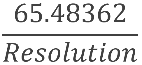](https://bookstack.vps-da8d40f3.arunmicro.com/uploads/images/gallery/2023-11/amax-1.png) Where resolution is the microstep resolution 8, 16, 32, 64, 128 or 256 |
| Maximum: | 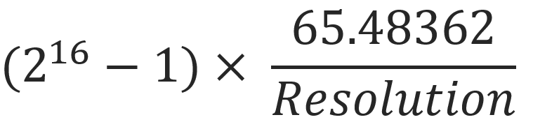 Where resolution is the microstep resolution 8, 16, 32, 64, 128 or 256 |
| Tx: AMAX,150<CR><LF> Rx: 0x0000,0x0000,1.5000E+02,1.4988E+02<CR><LF> Tx: AMAX<CR><LF> Rx: 0x0000,0x0000,1.5000E+02,1.4988E+02<CR><LF> | // Set acceleration to 150Hz/s // Note that the target value of 150 has been adjusted to the closest real value, which deviates from the requested value by 0.12 Hz/s |
| Tx: DMAX,150<CR><LF> Rx: 0x0000,0x0000,1.5000E+02,1.4988E+02<CR><LF> Tx: DMAX<CR><LF> Rx: 0x0000,0x0000,1.5000E+02,1.4988E+02<CR><LF> | // Set deceleration to 150Hz/s // Query deceleration |
| Tx: VSTART,0<CR><LF> Rx: 0x0000,0x0000,0.0000+00,0.0000+00<CR><LF> Tx: VSTART<CR><LF> Rx: 0x0000,0x0000,0.0000+00,0.0000+00<CR><LF> | // Set VSTART to 0 Hz // Query VSTART |
| Tx: VSTOP,10<CR><LF> Rx: 0x0000,0x0000,1.0000+01,9.9996+00<CR><LF> Tx: VSTOP<CR><LF> Rx: 0x0000,0x0000,1.0000+01,9.9996+00<CR><LF> | // Set VSTOP to 10 Hz // Query VSTOP |
| \[Default: | 1 kHz\] |
| Minimum: | 1 Hz |
| Maximum: | 15 kHz |
| Tx: VMAX,1000<CR><LF> Rx: 0x0000,0x0000,1.0000E+03,1.0000E+03<CR><LF> Tx: VMAX<CR><LF> Rx: 0x0000,0x0000,1.0000E+03,1.0000E+03<CR><LF> | // Set VMAX to 1 kHz // Query VMAX |
| Tx: VACT<CR><LF> Rx: 0x0000,0x0000,1.0000E+03<CR><LF> | // Query state of blink |
| \[Default: | 0\] |
| Minimum: | -223 |
| Maximum: | 223-1 |
| Tx: PACT<CR><LF> Rx: 0x0000,0x0000,1000.00<CR><LF> Tx: PACT,0<CR><LF> Rx: 0x0000,0x0000,0.00<CR><LF> | // Query actual position // Set actual position 0 |
| \[Default: | 0\] |
| Minimum: | -223 |
| Maximum: | 223-1 |
| Tx: PREL<CR><LF> Rx: 0x0000,0x0000,1000.00<CR><LF> Tx: PREL,0<CR><LF> Rx: 0x0000,0x0000,0.00<CR><LF> | // Query relative position // Set relative position 0 |
| \[Default: | 0\] |
| Minimum: | 0 |
| Maximum: | 2796 |
| Tx: TZW,100<CR><LF> Rx: 0x0000,0x0000,1.0000E+02<CR><LF> Tx: TZW<CR><LF> Rx: 0x0000,0x0000,1.0000E+02<CR><LF> | // Set TZW to 100 ms // Query TZW |
| \[Default: | 10000 Hz\] |
| Minimum: | 1 Hz |
| Maximum: | 15000 Hz |
| Tx: THIGH,500<CR><LF> Rx: 0x0000,0x0000,5.0000E+02,5.0400E+02<CR><LF> Tx: THIGH<CR><LF> Rx: 0x0000,0x0000,5.0000E+02,5.0400E+02<CR><LF> | // Set THIGH threshold to 500 Hz // Query THIGH |
| Tx: EDGE,1<CR><LF> Rx: 0x0000,0x0000,1<CR><LF> Tx: EDGE<CR><LF> Rx: 0x0000,0x0000,1<CR><LF> | // Set EDGE to rising edge // Query EDGE |
| \[0: | Normal; each step input will cause one step at the current resolution\] |
| 1: | Interpolate; each step input will be interpolated to 256 microsteps. |
| Tx: INTERP,1<CR><LF> Rx: 0x0000,0x0000,1<CR><LF> Tx: INTERP<CR><LF> Rx: 0x0000,0x0000,1<CR><LF> | // Set interpolation to 256 microstep on // Query INTERP |
| \[Default: | 150 °C\] |
| Minimum: | 0 °C |
| Maximum: | 200 °C |
| Tx: BAKET,100<CR><LF> Rx: 0x0000,0x0000,100<CR><LF> Tx: BAKET<CR><LF> Rx: 0x0000,0x0000,100<CR><LF> | // Set bake setpoint to 100 °C // Query BAKET |