# SMD4 User Manual
UHV Stepper Motor Drive
# Introduction
[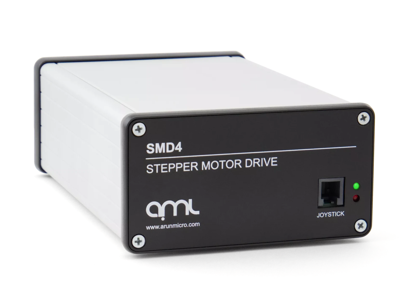](https://bookstack.vps-da8d40f3.arunmicro.com/uploads/images/gallery/2023-11/smd4-1-transparent.webp)
The SMD4 stepper motor drive is a single-axis bipolar stepper motor drive, intended for use with AMLs range of vacuum-compatible stepper motors (VCSMs). It maximises motor performance while minimising temperature rise.
Powerful software is supplied with the SMD4 that enables you to easily control and configure multiple SMD4 units
simultaneously, in a single, user-friendly graphical interface. For advanced users, the drive can also be controlled via scripting in JavaScript.
The drive features extensive communications options, including USB, RS232, RS485 and Ethernet. It also includes an innovative boost feature; this uses an internal circuit to increase the 48 V input up to 67 V for driving the motors. This allows the use of standard 48 V power supplies without compromising on motor performance.
The drive supports incremental and absolute BiSS encoders (when so equipped). This enables features including closed loop control and virtual limits based on encoder position and greatly expands the features of the product.
### Liability and warranty
AML assumes no liability and the warranty becomes null and void if the end-user or third parties:
- Disregard the information in this document
- Use the product in a non-conforming manner
- Make any kind of alterations (modifications, repair work, etc.) to the product
- Use the product with accessories not listed in the corresponding product documentation
We reserve the right to make technical changes without prior notice. The figures are non-committal.
# Safety and warning notices
**WARNING!** All work described in this document may only be carried out by persons who have suitable technical training and the necessary experience or who have been instructed by the end-user of the product.
The safety of any system incorporating the instrument is the responsibility of the assembler of the system.
Use the instrument only as specified in this manual, otherwise the protection provided by the instrument might be impaired.
**Ignoring this or subsequent safety information could lead to personal injury, or malfunction or permanent damage to the equipment.**
# Technical information
### General
| Dimensions | 166 mm x 106 mm x 56 mm
(excluding connectors and feet) |
| Weight | 0.5 kg |
| Protection class | IP 20 |
| Temperature | Operation 10°C to 60°C,
Storage -10°C to 85°C |
| Power requirements | 48 Vdc ± 5%
Power supply is included.
|
| Power consumption | 48 W max.
|
| Safety compliance | EN 61010-1-2010 |
| EMC compliance | Emissions EN61800-3:2018, EN55032 Class B, 3m (As 61800-3:2018, Table 17, Category C1, first environment)
Immunities, EN55035, basic electromagnetic environment |
| Type | 2 phase bipolar stepper motor driver for 4-lead motors |
| Phase current | Up to 1 A RMS, adjustable in 30 mA steps |
| Source voltage | 67 Vdc maximum
48 Vdc supply is boosted to 67 Vdc.
Boost function can be disabled if required. |
| Resolution | Full, 8, 16, 32, 64, 128, 256 micro-stepping
Stops on full step positions only, micro-stepping is used for control of resonance and smoother step transition. |
| Step frequency | 1 Hz to 15 kHz |
| Protection | Short to ground and phase to phase |
| Supported types | Digital incremental and BiSS absolute |
| Power | 5V at 250 mA max. is available to power the encoder, protected by self-resetting fuse. |
| Connection | Female 26 way high density D-Sub.
Encoder connects via adapter cable according to encoder type.
Adapter cables for supported encoders are available from AML.
|
| Incremental encoder support | Digital (RS422) incremental encoders having differential A, B and Z signals.
Single ended P and Q limits signals are supported.
Maximum clock rate 1 MHz.
|
| Absolute encoder support | 26 bit BiSS-C (support for other bit depths may be added via firmware update) |
| Type | Selectable PT100 RTD or K-Type thermocouple |
| Range | -200°C to 240°C |
| Accuracy | ±15 °C for thermocouple, ±5 % for RTD |
| Fault detection | RTD: Open and short-circuit
Thermocouple: Open circuit only |
| • Remote – Control and configure via USB, Ethernet or Serial
• Step, Direction Enable (SDE) – For connection to an external motion controller or PLC
• Bake – Programmed cycle to heat the motor while stopped to drive off adsorbed gasses |
| USB | USB 2.0 Full Speed via USB-C connector
Virtual COM port and firmware update interface |
| Ethernet | 10/100 Base-T, auto MDI-X, RJ45 8P8C connector
Telnet (port 11312) |
| Serial communication | Selectable RS232 or RS485 mode (shared pins)
Dual RJ45 8P8C connectors allow daisy chaining multiple devices in RS485 mode
User selectable termination in RS485 mode
115200 default and maximum baud rate |
| Compatibility | Windows 10 or later |
| API | C# and Python APIs are available |
| Type | Optocoupled, common cathode |
| Levels | 3.3 Vdc to 5 Vdc maximum
Higher voltages require external current limiting resistor |
| Maximum frequency | 2 MHz at 50% duty
Maximum full-step rate limited to 7.8 kHz for micro-step resolution of 256. |
| Quantity | 2 |
| Compatible switch types | Mechanical NO or NC (polarity selectable) |
| Protection | Withstands continuous short to 12 V maximum |
| Connection | Front panel mounted 4P4C jack with auto-detection of connection state |
| Input type | Active low, short to ground to activate function |
| Miscellaneous | Open circuit voltage 3.3 V, source current < 3.5 mA |
### Mechanical
All dimensions are in millimetres.
[ 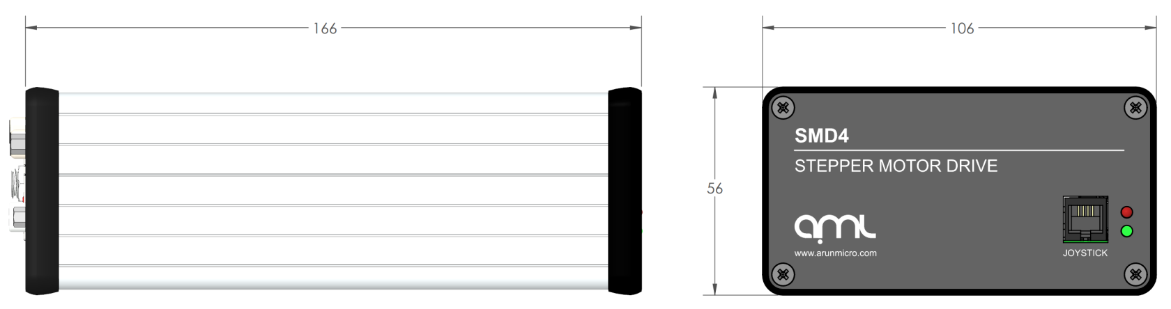 ](https://bookstack.vps-da8d40f3.arunmicro.com/uploads/images/gallery/2023-11/smd4-datasheet-drawing.PNG)
### Scope of delivery
| 1 | SMD4 |
| 1 | USB Type-A to USB Type-C lead |
| 1 | Power supply |
### Accessories
The following accessory items are available from AML.
| SMD3JOY
| Joystick (compatible with SMD4)
|
| CAB-D15D9
| SMD4 Motor Cable, 3m, D-Sub 15 Male to D-Sub 9 Female
|
| CAB-D15MLF
| SMD4 Motor Cable, 3m, D-Sub 15 Male to MLF18
|
| CAB-3D15MLF
| SMD4 Motor Cable, 3m, 3X D-Sub 15 Male to MLF18
|
| CAB-D26D15
| SMD4 Encoder Cable, Incremental, 3m, HD D-Sub 26 Male to D-Sub 15 Female
|
| CAB-D26D9
| SMD4 Encoder Cable, Absolute, 3m, HD D-Sub 26 Male to D-Sub 9 Female
|
# Installation
### Before installation
**WARNING:** Read this manual carefully before installing and operating the SMD4. Observe the following safety instructions.
**WARNING:** All work described in this document may only be carried out by persons who have suitable technical training and the necessary experience or who have been instructed by the end-user of the product.
**WARNING:** Without proper training and necessary experience, damage to the equipment or personal injury might result.
**DANGER:** Danger of electric arcing! Never plug or unplug any connector while powered. Plugging or unplugging a motor while powered may damage or destroy the driver output stage.
### Unpacking
On receipt of the instrument remove all packing material and check that all items on the delivery note have been received. Report any damage or shortages to the company or distributor who supplied the instrument. The packing material has been specially designed to protect the instrument and should be retained for possible future use.
### Mechanical installation
The SMD4 is a freestanding instrument. It does not require mounting. Forced air ventilation is not required. The ambient operating temperature range is 10 °C to 60 °C.
### Front and rear panels overview
#### Rear panel
Most connections including power, communications and motor are on the rear panel. AML offer several air side cable options for making the connection between motor, encoder, and chamber feed throughs, see [motor wiring overview](https://bookstack.vps-da8d40f3.arunmicro.com/link/27#bkmrk-motor-wiring). Communications leads such as USB and network are readily available off the shelf.
[](https://bookstack.vps-da8d40f3.arunmicro.com/uploads/images/gallery/2025-06/smd4-rear-flat-render.JPG)
#### Front panel
The front panel hosts status lights, see [troubleshooting](https://bookstack.vps-da8d40f3.arunmicro.com/link/32#bkmrk-page-title) and the joystick port.
[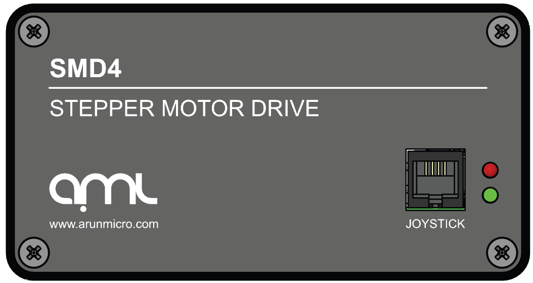](https://bookstack.vps-da8d40f3.arunmicro.com/uploads/images/gallery/2024-02/dVMimage.png)
### Power
| Connector: Barrel power jack
2.1 mm pin, 5.6 mm hole
|
| [](https://bookstack.vps-da8d40f3.arunmicro.com/uploads/images/gallery/2024-03/Uv8dc.png)
| 48 Vdc input. Centre positive.
|
Power input for both internal logic circuits and the motor itself.
The power supply must:
- Meet the requirements set out in the [technical information](https://bookstack.vps-da8d40f3.arunmicro.com/books/smd4-user-manual/page/technical-information "Technical information") section of this document
- Provide reinforced or double insulation between mains and supply output
- Include protection against short circuit
A suitable power supply is included with the equipment.
**DANGER:** Danger of electric arcing! Never plug or unplug the power connector while powered.
### Communications
Configure and control the SMD4 using AML Device Control software, available as a free download from our website at [https://arunmicro.com/documents/software/](https://arunmicro.com/documents/software/)
Alternatively, use a terminal program, or your own application. APIs are available to help customers implement their own applications faster, see [here](https://bookstack.vps-da8d40f3.arunmicro.com/link/93#bkmrk-page-title) for details.
This section details the available interfaces.
#### USB
| Connector: USB-C
|
| [](https://bookstack.vps-da8d40f3.arunmicro.com/uploads/images/gallery/2024-03/x5.png)
| |
USB Type-C connection. The connection is reversible, and the plug may be inserted either way up.
The SMD4 appears as a virtual COM port when connected to the PC. No additional drivers are required.
#### LAN
| Connector: 8P8C RJ45
RJ45, 8 poles, 8 connections
|
| [](https://bookstack.vps-da8d40f3.arunmicro.com/uploads/images/gallery/2024-03/lan.png)
| |
10/100M network connection with Auto MDI-X.
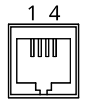
#### RS232/485
| Connector: 8P8C RJ45
RJ45, 8 poles 8 connections
|
| [](https://bookstack.vps-da8d40f3.arunmicro.com/uploads/images/gallery/2024-03/rs232.png)
| 1 | |
| 2 | |
| 3 | |
| 4 | A+/Tx |
| 5 | B-/Rx |
| 6 | |
| 7 | |
| 8 | GND |
RS232 and RS485 share pins. Before connecting to them, use an alternate interface (USB or LAN) to configure the desired mode of operation. Undefined behaviour will result if the SMD4 is connected to an RS485 network when in RS232 mode or vice-versa.
There are two identical connectors, allowing SMD4 devices to be daisy-chained together.
An optional termination resistance can be enabled if required. This would typically be enabled on the last device on the bus, to reduce reflections and maintain signal integrity. The usage of this feature should be evaluated in the final system.
Configure the mode of operation (RS232 or RS485) before plugging a connector in. Do not make changes to the mode without first disconnecting both connectors. Undefined behaviour will result if the SMD4 is connected to an RS485 network when in RS232 mode or vice-versa.
##### Bussing
The dual connectors allow multiple SMD4s (or other devices) to be bussed together. There are several important considerations to be aware of when doing so:
- RS232 is not well suited to multi-drop; use RS485 for this purpose if at all possible. If using RS232, devices can receive and process commands, but will not respond and data cannot be returned to the host.
- Ensure all devices on the bus are in the the same mode (RS232 or RS485) and the same serial configuration (baud rate, etc.) matches between devices.
- When using text protocol, begin all commands with the '@' addressing prefix. This places the SMD4 into addressing mode which brings into force alternate communication rules that allow the SMD4 to function properly on a bus with other devices. This is discussed in the [Addressing](https://bookstack.vps-da8d40f3.arunmicro.com/link/51#bkmrk-addressing) section.
- Do not use text protocol commands without the addressing prefix. This will cause multiple devices to respond at once and the resulting bus contention may result in undefined behaviour.
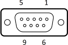
### Motor
Read this section to learn about wiring up the motor, including air and vacuum side connections.
| Connector: DA15-F
D-Sub, 15 ways, female
|
| [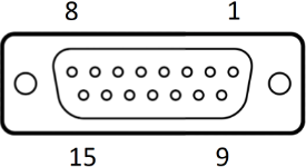](https://bookstack.vps-da8d40f3.arunmicro.com/uploads/images/gallery/2024-03/d-sub-15.png)
| 1 | Phase B2 |
| 2 | Phase B1 |
| 3 | Phase A2 |
| 4 | Phase A1 |
| 5 | Limit 1 |
| 6 | Limit 2 |
| 7 | Thermocouple negative |
| 8 | Thermocouple positive |
| 9 | GND
|
| 10 |
| 11 |
| 12 |
| 13 | RTD B2 |
| 14 | RTD B1 |
| 15 | RTD A |
**DANGER!** Danger of electric arcing! Never plug or unplug the connector while powered! Plugging or unplugging motor while powered may damage or destroy the driver output stages.
#### Limit switch inputs
There are two limits inputs; they can be configured to stop the motor when either is triggered. A limit input is triggered by shorting it to 'GND', usually with a mechanical switch mounted on the mechanism that the motor is driving. Logic level signals, for example, from optical or hall effect sensors may also be used.
Input polarity can be reversed to accommodate normally open or normally closed switches.
Limit 1 applies when the motor position counter is incrementing, and limit 2 applies when the motor position counter is decrementing.
Limits inputs include a pullup resistor. See section [Limits](https://bookstack.vps-da8d40f3.arunmicro.com/link/28#bkmrk-limits) for details.
**INFORMATION:** Limits inputs are duplicated on the I/O connector for maximum user flexibility in arranging wiring for the system. Limit signals on both this and the I/O connector are electrically connected. Do not apply different electrical potentials between like-named limits inputs otherwise a short will occur between the two.
#### Thermocouple
The thermocouple lead for motors equipped with the standard K-Type thermocouple should be connected here. If using a motor equipped with an RTD, this connection may be left open. Be sure to select the correct sensor type, see section [Temperature sensor selection](https://bookstack.vps-da8d40f3.arunmicro.com/books/smd4-user-manual/page/operation#bkmrk-temperature-sensor-s).
**INFORMATION:** To provide greater convenience in wiring to the vacuum chamber, the thermocouple input is included on the motor connector, rather than a dedicated micro K-Type thermocouple connector. This comes at the cost of reduced accuracy due to the parasitic thermocouple junctions that exist within the connector. This is accounted for by the looser accuracy specification for the thermocouple input over the RTD one, and a generous tolerance in the motor over temperature threshold as further insurance. Nonetheless, accuracy can be improved by avoiding large temperature gradients across the SMD4; for example, avoid placing the rear panel of the product in direct line of hot exhaust from other equipment.
#### RTD
For motors equipped with an RTD instead of a thermocouple, make the RTD connection here. If the RTD is not required, leave the connections open.
The RTD input is compensated for cable length by the three-wire connection.
#### Motor wiring overview
Connecting motors inside a vacuum chamber to the SMD4 comprises two tasks:
- Wiring the motor to a vacuum feedthrough installed in the chamber wall.
- Wiring the vacuum feedthrough to the SMD4.
AML supply vacuum feedthroughs, ready-made cabling, and components allowing custom cables to be easily manufactured. A typical setup is shown below and used for illustration throughout this section.
[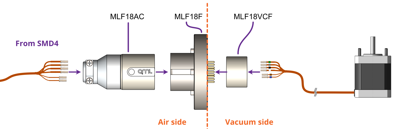](https://bookstack.vps-da8d40f3.arunmicro.com/uploads/images/gallery/2024-02/smd4-to-feedthrough-connection.png)
**INFORMATION:** Verify that the motor is working correctly before sealing the vacuum chamber. Rectifying mistakes afterwards is inconvenient.
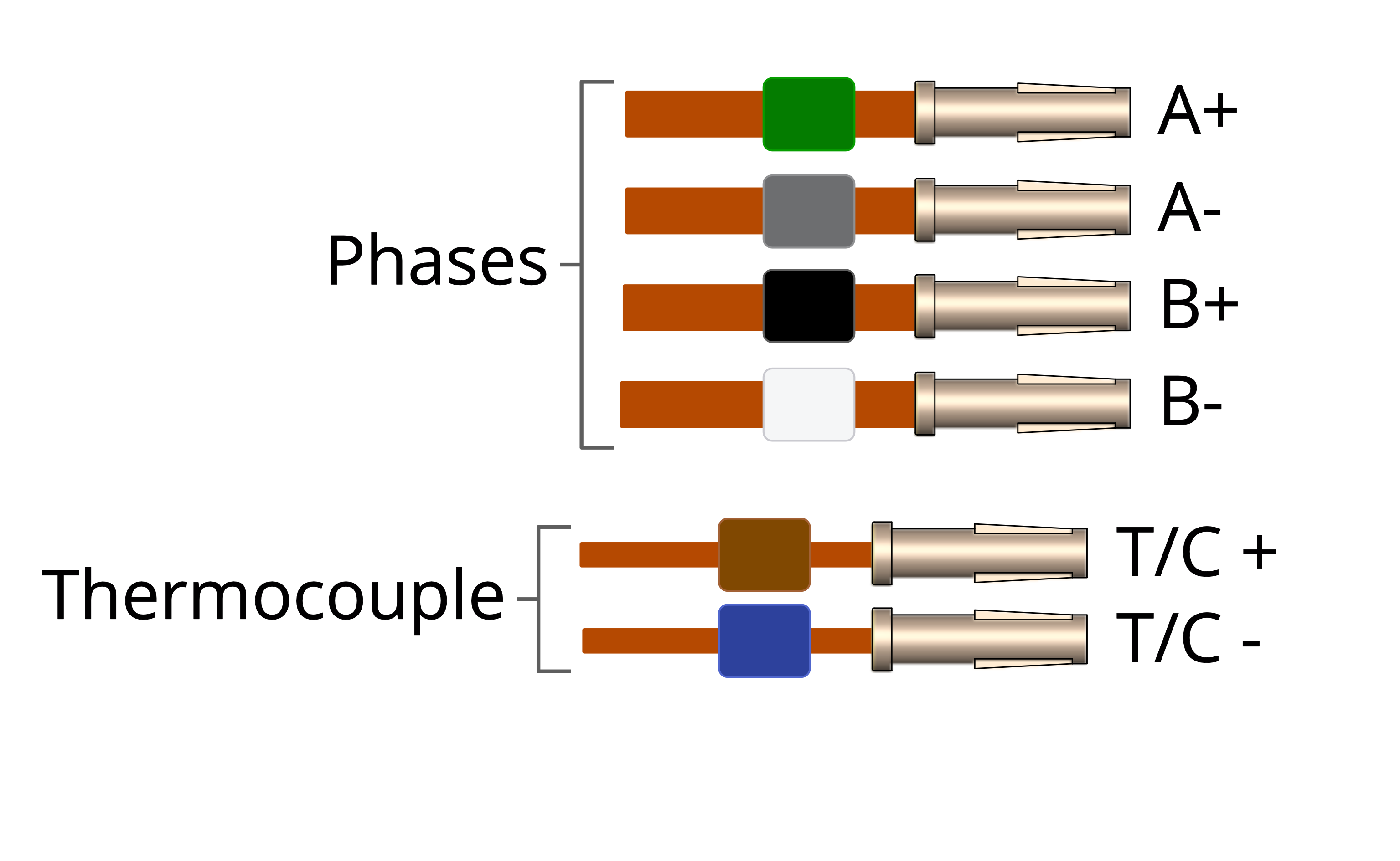
#### Getting familiar with the motor leadouts
The motor leadout wires are polyimide film-wrapped, silver-plated OFHC solid copper and each is fitted with a 1.5 mm crimp socket terminal. The leads have a distinctive reddish/orange color. Each lead has a UHV compatible coloured glass bead fitted at the crimp end for identification. The phase leadout wires are much thicker than the thermocouple leadouts.[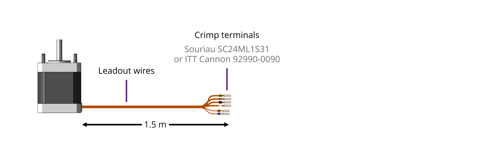](https://bookstack.vps-da8d40f3.arunmicro.com/uploads/images/gallery/2023-10/motor-leadout-wires-illustration-2.png)
| Motors equipped with a ***Thermocouple:*** | Motors equipped with an ***RTD:*** |
| [](https://bookstack.vps-da8d40f3.arunmicro.com/uploads/images/gallery/2023-10/motor-leadout-wires-rtd-illustration.png) | [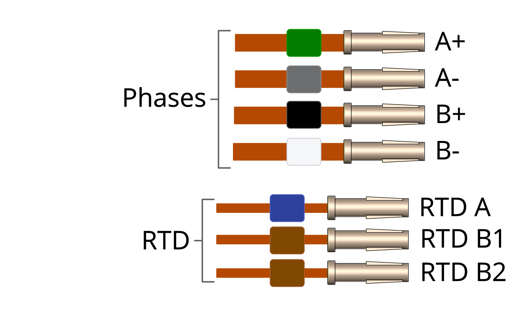](https://bookstack.vps-da8d40f3.arunmicro.com/uploads/images/gallery/2023-10/motor-leadout-wires-rtd-illustration.png) |
When working with the motor leads:
- Keep the leadout wires of each phase twisted together (A+ and A- twisted together, B+ and B- twisted together)
- Keep the thermocouple or RTD leads twisted together
#### Identifying the leadouts when coloured beads are missing
If the identification beads are missing, the wires can be identified using an inexpensive multimeter, and a magnet. The multimeter must be capable of measuring resistance with a resolution of about 1 ohm.
**Phase leadouts**
These are the four thicker leadouts. Identify the two motor phases by their resistance, which will be in the range of 3 to 15 ohms, depending on the motor type. There is no electrical connection between the two phases, to the thermocouple/RTD or the case of the motor. Most of the resistance is in the windings of the motor and is virtually unaffected by shortening of the leads. Connect each phase to the appropriate drive terminals. The resistance of the wires from the feedthrough to the drive must be less than a few ohms.
| **Thermocouple Leadouts**
The thermocouple wires are much thinner than the phase leads, and there are two of them. If three wires are present, the motor has an RTD installed, see below for details. The thermocouple is insulated from the rest of the motor.
The two leads are of different material; one is made from Alumel, which is weakly magnetic, and the other Chromel, which is not. Use a magnet to find the Alumel wire, then connect as shown below.
| | Lead | Connected to terminal marked | | Alumel | Alumel, N, - (minus) or coloured blue |
| | Chromel | Chromel, P, + (plus) or coloured brown | |
|
| **RTD Leadouts**
As per the thermocouple leads, but three instead of two leads. These must be identified by resistance; one pair of wires are connected at the motor end. These will measure a few ohms depending on cable length and are the ‘B1’ and ‘B2’ connections, which are interchangeable.
The remaining wire is the ‘A’ connection and should measure around 100 ohms to either ‘B1’ or ‘B2’.
| | Lead | Connected to terminal marked | | A | A, or coloured blue |
| | B1 | Chromel,B1, or coloured brown | | | B2 | B2, or coloured brown | |
|
#### Reversing motor direction
If the motor direction is opposite to that required, simply swap the wires of one phase to reverse direction of rotation. For example, swap the A+ and A- leads and the motor will spin the other way.
#### Wiring the motor to a vacuum feedthrough
AML motors are commonly connected via an MLF18 feedthrough or a standard D-Sub feedthrough, but any suitable feedthrough may be used. This section discusses these options.
##### **9-Way D-Sub**
The VC9D-40CF 9-way D-Sub male feedthrough is suitable for one motor fitted with either a thermocouple or 3-wire RTD. The standard crimp terminals supplied with AML motor leadout wires should be removed and replaced with a VC9DF PEEK D-Sub female connector and crimp terminals. An optional VC9DB cable strain relief is also available.
[](https://bookstack.vps-da8d40f3.arunmicro.com/uploads/images/gallery/2024-03/dsub9-expanded.PNG)
**Motor wires pinout for the VC9DF**
The illustration below shows the view into the non-mating side of the connector, into which the motor leads should be inserted, as shown below. Pass the wires through the backshell before crimping.
| Connection | Colour | Pin | Pin Insertion Side |
| Phase A1 | Green | 4 | [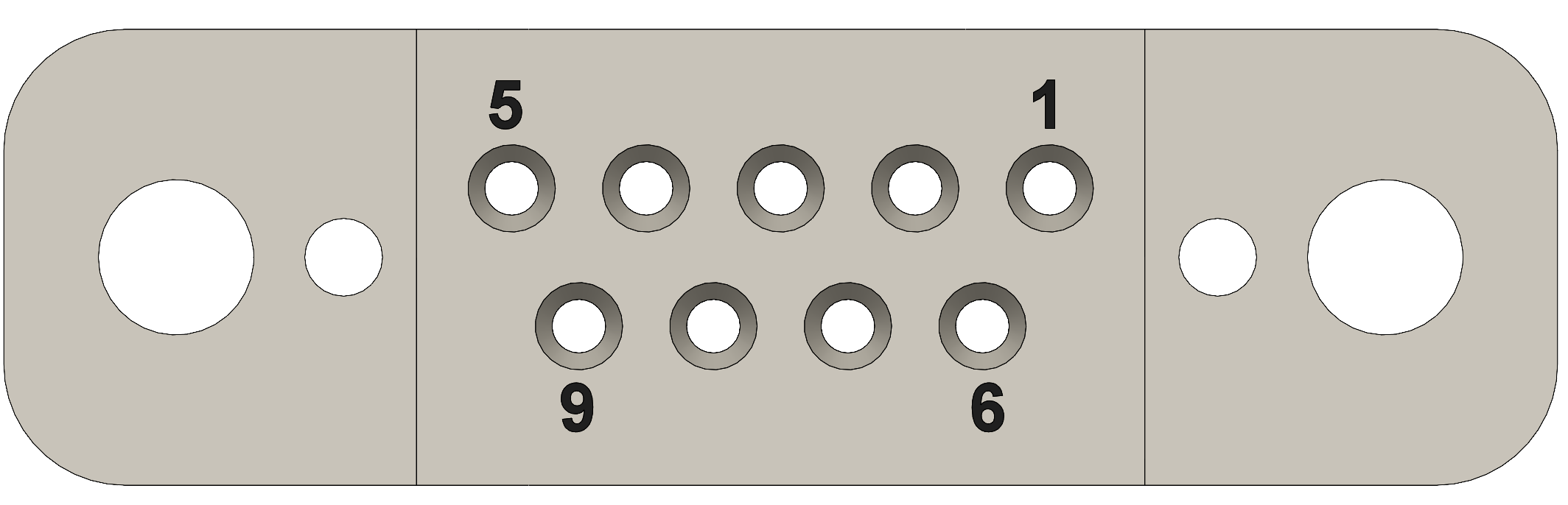](https://bookstack.vps-da8d40f3.arunmicro.com/uploads/images/gallery/2024-03/d-sub9-female.PNG) |
| Phase A2 | Grey | 3 |
| Phase B1 | Black | 2 |
| Phase B2 | White | 1 |
| Thermocouple + | Brown | 8 |
| Thermocouple - | Blue | 7 |
| RTD A | Blue | 5 |
| RTD B1 | Brown | 6 |
| RTD B2 | Brown | 9 |
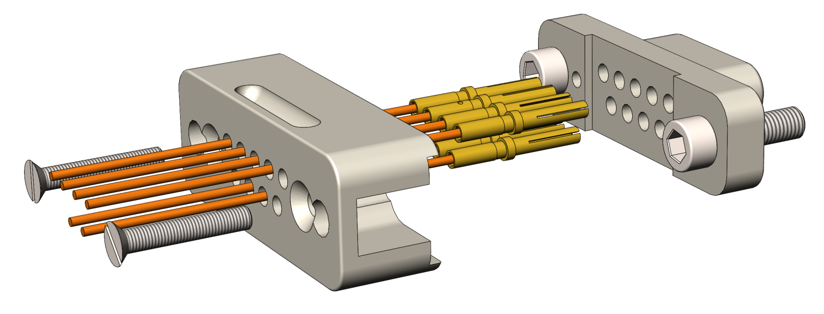
##### **18-Way MLF18**
The MLF18F feedthrough has 18 x 1.5 mm gold-plated feedthrough pins and is suitable for up to three motors fitted with thermocouples or up to two motors fitted with 3-wire RTDs. An internal bakeable connector, MLF18VCF, is available into which the crimp terminals on the motor leads are inserted. This significantly reduces the risk of short-circuits and makes the installation more convenient.
| Using the MLF18F feedthrough and MLF18VCF vacuum side connector: | Alternatively, plug crimps directly onto the feedthrough pins of the MLF18F: |
| [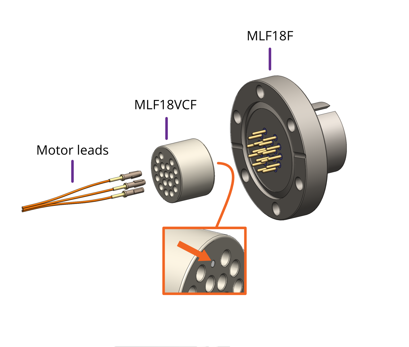](https://bookstack.vps-da8d40f3.arunmicro.com/uploads/images/gallery/2023-10/vacuum-side-motor-connection-mlf18vcf.png)
| [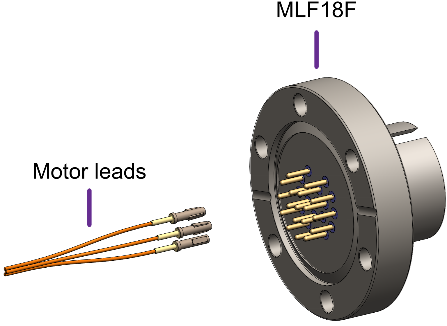](https://bookstack.vps-da8d40f3.arunmicro.com/uploads/images/gallery/2023-10/vacuum-side-motor-connection-straight-into-mlf18f-3.png)
|
| Mating side identified by dot. Motor lead terminals should be inserted in the other side. |
|
| **Standard pinout for the MLF18VCF** |
| The illustration below shows the view into the non-mating side of the connector, into which the motor leads should be inserted, as shown below. |
| Connection | Colour | Motor 1 | Motor 2 | | Phase A1 | Green | 1 | 7 | | Phase A2 | Grey | 3 | 9 | | Phase B1 | Black | 2 | 8 | | Phase B2 | White | 4 | 10 | | Thermocouple + | Brown | 5 | 11 | | Thermocouple - | Blue | 6 | 12 | | RTD A | Blue | 13 | 16 | | RTD B1 | Brown | 14 | 17 | | RTD B2 | Brown | 15 | 18 |
| [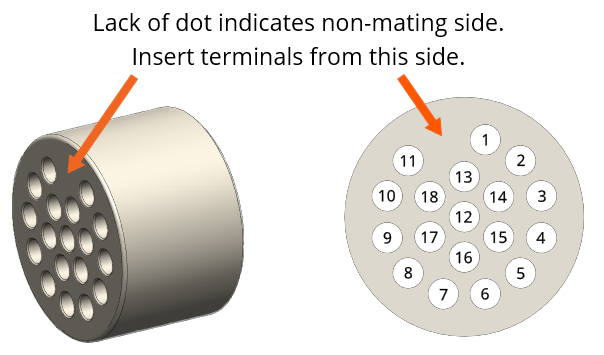](https://bookstack.vps-da8d40f3.arunmicro.com/uploads/images/gallery/2023-10/mlf18ac-pinning.png) |
##### **Using other feedthroughs**
AML stepper motors can be ordered with either a K-Type thermocouple, or 3-wire PT100 RTD. The former requires 6 pins, and the latter 7 pins.
When using motors installed with a thermocouple, it is not necessary to use a thermocouple vacuum feedthrough or extension wires, as the error introduced by incompatible feedthrough material is usually less than 5 °C and the temperature measurement is not required to be very precise.
| **Preparation of motor leadouts for connection to other feedthroughs** |
| If making custom terminations for the motor leads, the installed crimps must be removed, and the wire ends stripped of insulation. Standard motors are fitted with Polyimide film-wrapped leads (illustrated below), and radiation-hard motors are fitted with polyimide-enamelled leads.
Polyimide is strong, flexible and abrasion-resistant and therefore difficult to strip. The simplest method of stripping polyimide film is to cut a ring with a sharp knife and withdraw the cylinder of insulation over the end of the wire.
Be careful not to mark the conductor surface with the knife. Strip the enamelled radiation-hard leads by scraping with a sharp knife. Either type of lead may be stripped with a suitable high-speed rotary stripper. Do not use a thermal stripper.
| [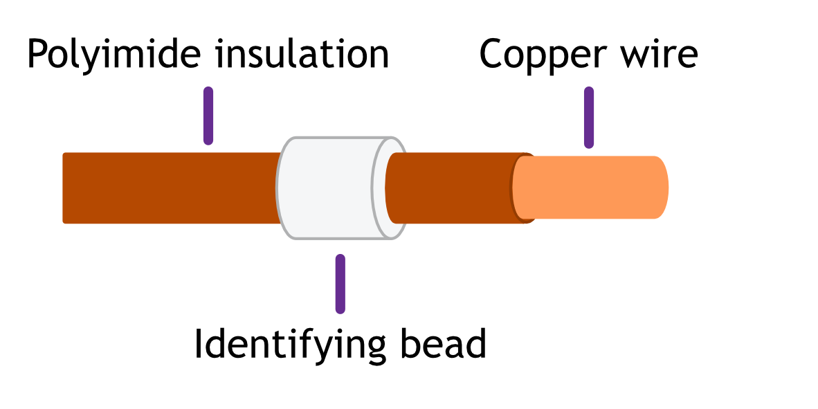](https://bookstack.vps-da8d40f3.arunmicro.com/uploads/images/gallery/2023-10/polyamide-wire-stripping.png) |
| **Rated voltage** | >= 300 V rms |
| **Rated current** | > 1.5 A rms |
| **Construction** | Twisted pairs plus overall screen.
Foil screen plus drain wire (of same or greater cross-sectional area as main cores) acceptable.
Foil plus braided screen better.
|
| **Resistance** | Maximum cable length is limited by the resistance of the cores; total round-trip cable resistance per phase should be kept to less than a few ohms.
Consult the cable manufacturer's data for these details. Excessive cable length causes a reduction in phase voltage at the motor compromising speed/torque characteristics.
The RTD circuit is compensated for cable length.
|
| **Qty. cores** | As required.
One motor requires 6 cores when fitted with a thermocouple, or 7 if fitted with an RTD
|
**Signal pairing:** Cable cores must be twisted together in pairs. This reduces radiated emissions from the cable and improves the immunity of the RTD and thermocouple signals to interference; use:
- One pair for phase A
- One pair for phase B
- One pair for thermocouple
- One pair for RTD signals A and B1, plus spare wire from another pair for B2.
Do not pair phase wires with temperature sensor wires.
**Wiring up to the MLF18AC airside connector**
The MLF18AC is supplied with comprehensive instructions detailing correct usage of the connector. The pinout to match with the standard MLF18F + MLF18VCF pinning described in section [Motor wiring](https://bookstack.vps-da8d40f3.arunmicro.com/books/smd4-user-manual/page/installation#bkmrk-motor-wiring) is shown below. Note that the illustration shows the MLF18AC looking into the non-mating side of the connector, i.e. the side into which crimps are inserted.
| Connection | Colour | Motor 1 | Motor 2 | | Phase A1 | Green | 1 | 7 | | Phase A2 | Grey | 3 | 9 | | Phase B1 | Black | 2 | 8 | | Phase B2 | White | 4 | 10 | | Thermocouple + | Brown | 5 | 11 | | Thermocouple - | Blue | 6 | 12 | | RTD A | Blue | 13 | 16 | | RTD B1 | Brown | 14 | 17 | | RTD B2 | Brown | 15 | 18 |
| Looking into the non-mating face of the MLF18AC, into which crimps are inserted
|
| [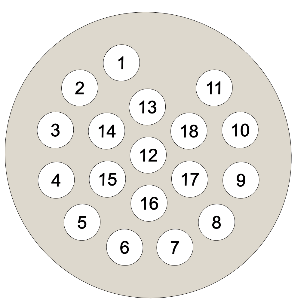](https://bookstack.vps-da8d40f3.arunmicro.com/uploads/images/gallery/2023-10/mlf18ac-pinning.png) |
### Encoder
| Connector: DA-26-F
D-Sub, 26 ways, female, high density.
|
| [](https://bookstack.vps-da8d40f3.arunmicro.com/uploads/images/gallery/2024-11/d-sub-26.png)
| 1 | 5V |
| 2 | BiSS MA- |
| 3 | BiSS MA+ |
| 4 | GND |
| 5 | BiSS SLO- |
| 6 | Reserved, do not make connection to this pin. |
| 7 | GND |
| 8 | 5V |
| 9 | GND |
| 10 | INC E |
| 11 | INC A- |
| 12 | INC A+ |
| 13 | INC B- |
| 14 | INC B+ |
| 15 | INC Z- |
| 16 | INC Z+ |
| 17 | INC P |
| 18 | INC Q |
| 19 | Reserved, do not make connection to this pin.
|
| 20 |
| 21 |
| 22 |
| 23 |
| 24 | BiSS SLO+ |
| 25 | 5V |
| 26 | GND |
### I/O
| Connector: DE9-F
D-Sub, 9 ways, female
|
| [](https://bookstack.vps-da8d40f3.arunmicro.com/uploads/images/gallery/2024-03/d-sub-9.png)
| 1 | GND |
| 2 | Fault (Output, open collector) |
| 3 | Limit 1/positive |
| 4 | Enable |
| 5 | Step |
| 6 | Reset fault (Input, active low) |
| 7 | Limit 2/negative |
| 8 | SDE COM |
| 9 | Direction |
#### Fault output and fault reset
The SMD4 disables the motor under certain fault conditions, see section [Faults](https://bookstack.vps-da8d40f3.arunmicro.com/books/smd4-user-manual/page/operation#bkmrk-faults). When this happens, the open collector ‘Fault’ output is set and may be used to signal to an external controller that the SMD4 is in a fault state.
Fault states are latching; once set the fault condition must be removed and the fault reset before normal operation may resume using either a remote interface command (see [CLR](https://bookstack.vps-da8d40f3.arunmicro.com/books/smd4-user-manual/page/communications-protocol#bkmrk-sys%3Aclr-%E2%80%93-clear-faul)) or pulling the ‘Reset fault’ signal to ‘GND’. This does not apply to the ‘EN’ (enable) input when in step direction mode, i.e. the enable input is not latching, and normal operation will resume immediately on restoring the enable input state. See section [Faults](https://bookstack.vps-da8d40f3.arunmicro.com/books/smd4-user-manual/page/operation#bkmrk-faults) for details.
#### Limits
Duplicated from the [motor connector](#bkmrk-limits).
#### Step, direction and enable
The step direction enable interface is an industry-standard interface allowing an external motion controller to generate stepping sequences, bypassing the SMD4’s internal motion controller. The inputs are galvanically isolated with three opto-isolators, and share a common connection, ‘SDE COM’. See section [Step/Direction](https://bookstack.vps-da8d40f3.arunmicro.com/books/smd4-user-manual/page/communications-protocol#bkmrk-step%2Fdirection) for details.
### Joystick
| [](https://bookstack.vps-da8d40f3.arunmicro.com/uploads/images/gallery/2023-10/lzGdtdpower-connector-pinout.png)
| 1 | GND |
| 2 | CW |
| 3 | CCW |
| 4 | DETECT |
For connection of a two-button joystick allowing basic motor control, for example, during commissioning. AML supply the SMD3 Joystick, part number ‘SMD3JOY’, which is compatible with the SMD4, for this purpose. The joystick can be used any time the SMD4 is in remote mode. See [here](https://bookstack.vps-da8d40f3.arunmicro.com/link/28#bkmrk-using-the-joystick) for more on joystick functionality.
If designing your own joystick or device to connect to this port:
- Inputs have internal pull-ups
- Activate the function by shorting ‘CW’, ‘CCW’ or ‘DETECT’ to pin 1, ‘GND’
- ‘DETECT’ is used to signal to the SMD4 that the joystick is plugged in, and thus should be left shorted to GND.
Logic level signals may also be used; 12 V max.
### Indicator lights
| **Green** | Status/power indicator
Blinks when the operation mode changes and while in bake.
|
| **Red** | Error indicator
On or flashing indicates and error. See section [Faults](https://bookstack.vps-da8d40f3.arunmicro.com/books/smd4-user-manual/page/operation#bkmrk-faults) for fault indications. When a fault is present, motor operation is disabled.
|
# Operation
Getting started
The quickest way to get started with the SMD4 and evaluate the features described in this section (having completed wiring up according to the previous chapter) is to install the SMD4 software on your PC (see [Software](https://bookstack.vps-da8d40f3.arunmicro.com/link/29#bkmrk-page-title) section), power on the SMD4 and connect it with the USB lead to the PC.
AML Device Control software allows one or more SMD4 units to be combined into a system and controlled individually or as a group. The software exposes all configuration items and makes it quick and easy to change any setting. Movements can be planned and executed. Live readouts of position, speed and status are presented.
Start the software, then click "Add device" in the top left corner. A list of available devices will appear. Click your device to select it, then click the 'Add device' button.
| [](https://bookstack.vps-da8d40f3.arunmicro.com/uploads/images/gallery/2024-11/add-device.png) | [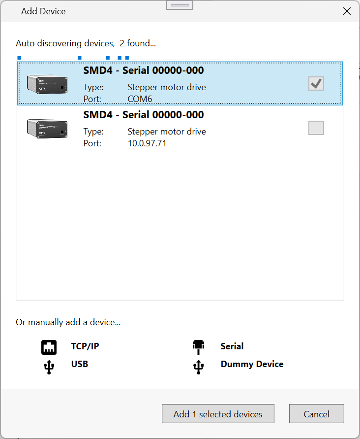](https://bookstack.vps-da8d40f3.arunmicro.com/uploads/images/gallery/2024-11/7IDimage.png)
|
Your new device appears in the tree on the left. It can be configured using the properties panel on the right hand side, while the central window shows speed, position and temperature readouts from the device, and provides controls for planning and making movements.
[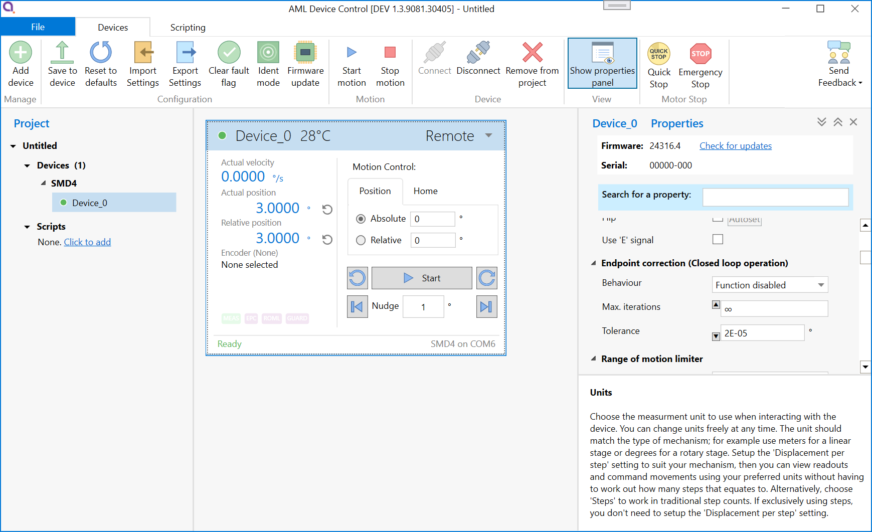](https://bookstack.vps-da8d40f3.arunmicro.com/uploads/images/gallery/2024-11/8x4image.png)See [here](https://bookstack.vps-da8d40f3.arunmicro.com/link/29#bkmrk-page-title) for more detail on the software.
#### Advanced users, system integrators
The remote interface uses a straightforward text based protocol, so it is easy to send commands to it using for example:
- Terminal applications
- Embedded systems
- Your own software
A C# API is available to speed up development of your own applications. Wrappers are available for other languages, including Python. The API is extensively documented and very quick to get up and running with. A quick start guide is available [here](https://bookstack.vps-da8d40f3.arunmicro.com/link/93#bkmrk-page-title).
The remote interface protocol is described in section [remote interfaces](https://bookstack.vps-da8d40f3.arunmicro.com/books/smd4-user-manual/page/remote-interfaces).
### Operating modes
The SMD4 has several operating modes:
- Normal - The default and usual operating mode
- Step and direction - Control the motor using an opto-isolated industry standard step direction interface
- Bake - Controlled heating of the motor to drive off adsorbed gasses
Configuration can be performed at any time and in any mode using one of the remote interfaces (USB, LAN or Serial).
Mode can be changed only when the motor is stopped, which can be determined from the standby flag returned in every communication, see [here](https://bookstack.vps-da8d40f3.arunmicro.com/link/51#bkmrk-status-flags-%28sflags). Unless otherwise noted, activities described in this manual are performed in normal mode.
### Persistence of settings
All changes made to the configuration via the remote interface are volatile (i.e. not retained on power cycling) unless the store command is executed before powering off. The AML Device Control software warns you of this when closing the application, but if writing a custom application to control the SMD4, your application must handle this if settings are to be persisted.
The SMD4 will always load the last stored settings on power on, or if the store command has not been previously used, defaults are loaded as per section [Command Reference](https://bookstack.vps-da8d40f3.arunmicro.com/link/51#bkmrk-command-reference). If settings become corrupted, for example, the write endurance of the memory in which the settings are stored is exceeded, the SMD4 loads defaults as identified above, and a fault indication is given, see section [Faults](https://bookstack.vps-da8d40f3.arunmicro.com/link/28#bkmrk-faults).
**INFORMATION:** Write endurance
The memory in which settings are stored has an endurance of about 1 Million write cycles. Only use the store command when necessary, for example, take care that your application does not perform multiple redundant store commands.
Remember to save your settings after making configuration changes!
### Units
Stepper motors work in steps, and as such the core unit of the SMD4 is steps. However, this is not always meaningful in the end application, so instead you can choose a preferred unit to work in, including:
- Meters, millimeters and microns
- Inches and thou
- Degrees, radians and revolutions
To use units other than steps, the displacement per step (distance the mechanism moves, per step) must be correctly configured. The chosen unit applies globally, for example:
- Command moves such as, move relative + 10 mm
- Specify speed as 27 mm/s
- Specify acceleration as 50 mm/s^2
- Configure virtual limits at -100 mm and +100 mm
You can freely switch between like units (e.g. meters and inches), and between any unit and steps. All values are automatically converted as required. There is no loss of precision when switching between steps and other units.
When working in units other than steps, your input may not translate into an integer number of steps. The SMD4 rounds such values to the closest integer step value internally at the time of use and at the latest possible point in the processing pipeline. Your original input is always preserved.
To use units other than steps, mechanism displacement per step must be configured correctly. This is typically called resolution in the mechanism documentation and is discussed later.
Unpredictable behaviour may result if units other than steps are used and mechanism displacement per step is not configured correctly.
### Mechanism setup and presets
There can be a a significant number of parameters to configure to prepare the SMD4 for use with a particular mechanism. This may include setting up encoders, limit switches, mechanism resolution and others.
The SMD4 has built in presets for most standard AML mechanisms to allow you to get up and running with a basic working configuration as quickly as possible. To use presets, locate the preset section in the properties and search for your mechanism in the list. You can enter partial or full part numbers to find your mechanism:
[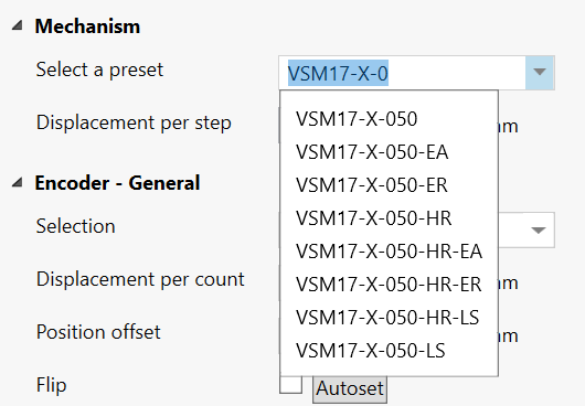](https://bookstack.vps-da8d40f3.arunmicro.com/uploads/images/gallery/2024-11/n2pimage.png)
Click on the desired mechanism to select it and apply the preset configuration. Review the new configuration by inspecting the SMD4 properties. Then, experiment cautiously to confirm that the mechanism is behaving as expected. Start by making small moves at low speed until confident that the setup is correct.
Before using the preset system, review the remainder of this manual to gain a proper understanding of the drive and how it operates, then return to this section.
Points to note regarding presets:
1. Several basic settings are always made (selecting an appropriate unit, displacement per step, encoder and limit switch configuration)
2. Only specific settings are changed according to the preset selected, all others are left untouched. The list of changes the preset system will make varies by preset and is not published. Presets reside in the SMD4 firmware and support for new mechanisms will be added as required via firmware update.
3. Various features are configured but not necessarily enabled. For example, limit switches if relevant are configured but no change is made to the global enable of limit switches, virtual limits are configured if relevant, but the virtual limit function enable state is not changed.
4. If an encoder is applicable, autoflip is executed to determine correct encoder orientation. This will cause the mechanism to move a small amount, see [here](https://bookstack.vps-da8d40f3.arunmicro.com/link/51#bkmrk-encoder).
5. Motor currents and profile are not changed. It is the users responsibility to configure these as required. This is discussed [here](https://bookstack.vps-da8d40f3.arunmicro.com/link/28#bkmrk-motor-current).
**WARNING:** It is the users responsibility to verify the changes that the preset system has made before using the mechanism, and to use appropriate caution and restraint in using the mechanism until it has been established that setup is correct.
### Basic motor configuration
Before running the motor, configure it first. A good order to approach this is:
- Select temperature sensor
- Configure motor currents
- Configure profile (speeds, acceleration ramps etc.)
The settings required will depend on your application and mechanism. The default settings provided are usually sufficient to get the motor spinning, but you'll need to adjust and refine these to suit. Read this section to learn more.
#### Steps
Stepper motors move in discrete increments, called steps. Typically there are 200 steps per revolution. When performed in quick succession, smooth continuous movement is possible. Precise movements can be made to a specific position by executing the desired number of steps. A step counter tracks the current step count, and position can be determined.
The number of steps is determined by the mechanical configuration of the motor itself. The motor drive applies varying patterns of current to the motor windings which pull the shaft to each motor step in turn and this is what results in rotation. The current applied to the motor determines how much torque is generated, and the rate at which the motor moves to each step position determines motor speed, called step frequency.
When turning the motor shaft by hand, you can feel a small 'notch' as you pass each step. This is called detent torque. The motor shaft aligns itself with the closest natural step position. Vacuum mechanisms are usually, and should be where possible, designed with balanced loads such that when the mechanism is moved to the desired place, the detent torque alone is enough to hold it in position and power can be removed from the motor.
#### Synchronicity
When the motor moves according to the sequence of steps it is driven with, it is said to be in sync, or maintaining synchronicity. Provided this condition is maintained, precise open loop control is possible. Open loop control is where movement is planned and made based on the assumption that the motor moved where it was commanded to.
Synchronicity can be lost under various circumstances, for example:
- Motor not powerful enough to move load
- Programmed acceleration is too fast for the motor to follow
- Inertia in the load overcomes the motor
Loss of sync may result in lost steps or a stall, in which the motor shaft stops rotating, or does so erratically.
#### Resonances
Stepper motors are susceptible to encountering resonances; mechanical oscillations that occur at particular operating points. Factors such as the mechanical load, speed and current all affect where and over what range resonances can occur. Resonance can result in loss of sync and or stall. Mechanisms are designed with this in mind, and aim to place any such resonances outside the applicable range of operating points. Microstepping and changes to the motor profile, discussed in the next sections can also be used to shift resonance points outside the desired area of operation.
### Temperature sensor selection
AML motors can be supplied with either a K-Type thermocouple or PT100 RTD temperature sensor. Ensure the sensor is connected to the thermocouple or RTD input on the motor connector, and make the appropriate selection. The temperature sensor select command allows selection between thermocouple and RTD.
If the temperature sensor was absent, misconnected, or the wrong type of sensor was selected, the drive may be in an error state which you'll need to clear before the motor can spin. See [here](https://bookstack.vps-da8d40f3.arunmicro.com/link/28#bkmrk-clearing-a-fault) for information on clearing faults.
**INFORMATION:** The motor is disabled if the temperature sensor is misconnected, faulty or the temperature measurement exceeds 190 °C in order to protect the motor from possible damage to the insulation material.
Check that the motor temperature sensor selection matches that of your motor.
When using a thermocouple, avoid significant temperature gradients across the thermocouple leads and connector on the SMD4.
### Motor currents
Different currents can be set for each phase of operation:
| Applies when
|
| Acceleration
| Motor is running but not at target frequency, i.e. during acceleration and deceleration. This allows you to set a higher current during acceleration (to overcome inertia of a large load, for example) and revert to a lower current once the load is moving, thus reducing motor power dissipation and extending run time. If you do not wish to use this feature, simply set acceleration current to equal run current.
|
| Run
| Current used when motor is at target run step frequency.
Must be set equal to or smaller than acceleration current. If a change to run current makes it greater than the acceleration current, the acceleration current is automatically adjusted to be equal to run current.
|
| Hold
| Motor is stopped and is only necessary where the motor detent torque is not enough to prevent undesirable movement of the load. The cost of using hold current is increased motor temperature under vacuum. Therefore, where possible, mechanisms should be designed to be statically balanced, and the hold current should be set to 0.
|
When the motor starts moving, acceleration current is applied immediately. When the motor stops after the deceleration, two additional states must be traversed before the acceleration current is reduced to hold current, first, a configurable delay during which acceleration current continues to be applied (called ‘standstill’ state), followed by a configurable delay during which acceleration current is reduced to hold current (called ‘going to standby’ state). This is shown in the graphic below:
| [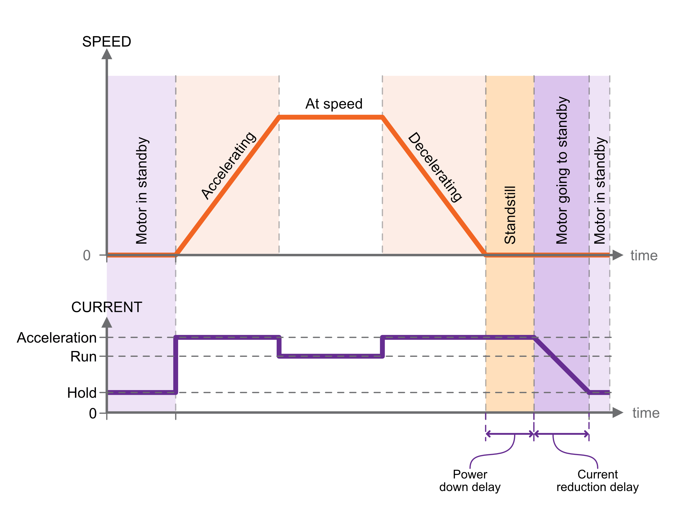](https://bookstack.vps-da8d40f3.arunmicro.com/uploads/images/gallery/2024-11/motor-currents.png) |
#### Standstill
Period after motor has stopped during which acceleration current is still applied. Adjustable between about 0 and 5.57 seconds using the ‘Power down delay’ setting \[PDDEL\]. Set to the minimum value suitable for your application to minimise heat generated.
#### Going to standby
Period during which acceleration current is gradually reduced to hold current. This smooth transition avoids a motor jerk on power down. Motor current is not continuously adjustable, instead being one of 31 discrete values from 0 to 1.044 A rms. Therefore, the current ramps down in steps. The step size may be set between 0 (instant power down) and 327 ms using the ‘Current reduction delay’ setting. Set to the minimum value suitable for your application to minimise heat generated.
#### Freewheel mode
Freewheel mode refers to how the motor is configured when it is at standstill and zero hold current is set. There are three choices:
- Use **freewheel** for minimum holding torque, which allows the motor shaft to be moved freely.
- **Phases shorted** for maximum holding torque with zero power applied to the motor (and so no heat generated in the motor).
- **Normal** offers some minimal amount of holding torque as a result of the phases still being connected to the driver circuitry.
### Profile
Learn how to configure microstepping and dynamic motor properties, such as speed, acceleration and deceleration. The profile settings apply for all modes except step direction mode.
The profile is configured with these general points in mind:
- Meeting the speed and torque requirements of the application
- Avoiding motor resonances that would disturb operation
- Maintaining synchronicity, avoiding step gain or loss
- Minimising temperature rise by using the lowest motor current required
The graphic below shows the basic profile:
| [](https://bookstack.vps-da8d40f3.arunmicro.com/uploads/images/gallery/2024-11/motor-currents.png)
|
#### Frequency and units
The term frequency is used throughout this manual in conjunction with motor dynamic properties, such as start frequency, step frequency and so on. This is a reference back to the way a stepper motor works; it rotates at a certain number of steps per second, or accelerates at some number of steps per second per second.
However, as discussed [here](https://bookstack.vps-da8d40f3.arunmicro.com/link/28#bkmrk-%C2%A0) recall that you can specify all these values in your chosen unit such as mm/s, or °/s^2. Where you see frequency, substitute you own unit as preferred.
#### Start and stop frequency
The start frequency is the initial step rate, and helps to allow the motor to overcome inertia and start moving smoothly; if start frequency were zero, the duration of the initial few steps might be long enough that the motor would overcome inertia on the first step, then effectively stop for a period of time, then have to overcome inertia once more for the second step, and so on, until the steps were frequent enough that the motor remains moving.
Stop frequency is the counterpart setting which determines the frequency for the last step.
Start frequency must be set equal to or smaller than stop frequency. This is enforced by the SMD4; if a change to the stop frequency makes it smaller than the start frequency, start frequency is automatically adjusted to be equal to stop frequency.
Start frequency and Stop frequency must be set equal to or smaller than Step frequency. The SMD4 will not force Start and Stop frequency to match Step frequency if either Start or Stop frequency are smaller than Step frequency.
#### Acceleration and deceleration
The SMD4 uses linear acceleration and deceleration ramps; velocity ramps up between the start frequency and the step frequency, and down linearly between the step frequency and stop frequency.
#### Zero wait time - Changing direction
When using higher values for the start and stop frequency, a subsequent move in the opposite direction would result in a jerk equal to start frequency + stop frequency. The motor may not be able to follow this. The zero wait time setting can be used to introduce a short delay between the two and eliminate the jerk.
#### Microstepping
Microstepping is applicable at low step frequencies (typically < 500 Hz) and helps reduce motor resonances resulting in smoother operation. In non-vacuum applications, it is also used to achieve increased positioning resolution, however, it requires energising both motor phases continuously even when the motor is stopped to maintain position, resulting in unacceptable levels of temperature rise in the motor in vacuum applications. Instead, mechanisms are designed to achieve the required positioning resolution with appropriate gearing.
Microstepping is not helpful at higher step rates, therefore, the SMD4 automatically switches between microstepping at low speeds and full step at high speeds. The transition point from full step to microstep is configurable, as illustrated below. Hysteresis is applied to this value resulting in the transition in the opposite direction (from microstep to full step) being at a slightly higher frequency, as illustrated above. Note that you cannot explicitly set the transition to full step point, only the transition from full step to microstep. The other transition is calculated automatically.
[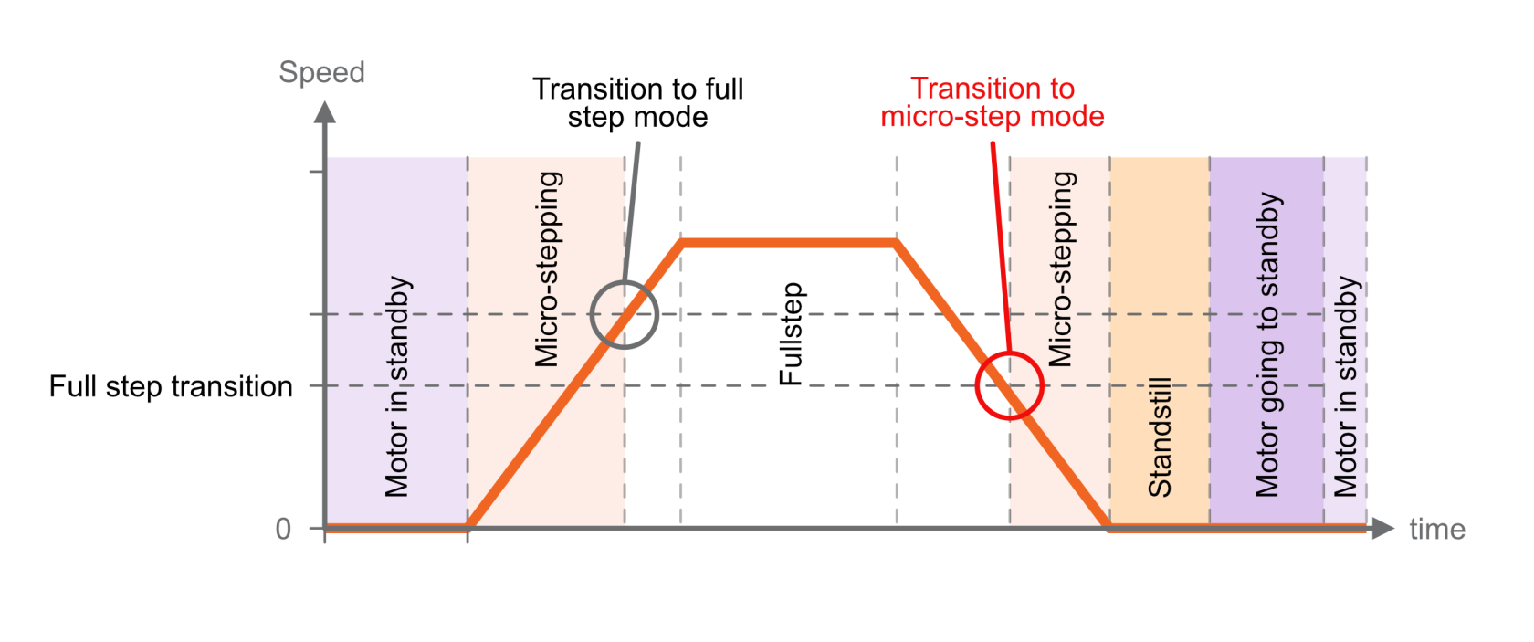](https://bookstack.vps-da8d40f3.arunmicro.com/uploads/images/gallery/2024-11/micro-stepping.png)
The resolution to use during microstepping is configurable, via the microstep resolution setting \[RES\]. Choices are 8, 16, 32, 64, 128 and 256. In all modes except for step/direction, the motor is only stopped in full-step positions. Microstepping is used exclusively for the purpose of smoothing the transition between steps, not to increase resolution.
The accuracy with which motor profile (acceleration, deceleration, etc.) settings may be made depends on the microstepping resolution; the maximum microstep resolution of 256 offers the greatest accuracy for these settings.
### Monitoring the motor
#### Temperature
Motor temperature can be read back from the remote interface, see [command MOTOR:T](https://bookstack.vps-da8d40f3.arunmicro.com/link/51#bkmrk-tmot-%E2%80%93-motor-tempera). The motor is shut down and the the drive enters a fault state if motor temperature exceeds 190 °C, or the temperature sensor is faulty, missing, or incorrectly configured.
#### Step/position counters
The SMD4 keeps track of position using two counters, absolute and relative position. These can be reset independently. The counters track motor step number, or index. The value may be fractional while the motor is spinning because of microstepping. When stopped the counter is always an integer value reflecting the fact that the drive only stops on full step positions.
When the counter reports a fractional value, the fractional part reflects a proportion of a full step. For example a counter value of 100.5 with microstepping resolution of 256 would mean the drive is executing microstep 128 of 256 on its way toward full step position 101. You don't need to consider microstep resolution when interpreting the counter value.
The counters behave differently with and without an encoder:
| **No encoder** | **Encoder used** |
| Counters reflect the internal step index counters that track the electrical step number that the drive thinks the motor is on.
The step counters are used to plan movement.
Provided the motor maintains synchronicity, this will equal the motor position.
| The counters are synchronized to the encoder position whenever a positioning cycle completes.
The encoder position (not the step counters) are used to plan moves, for example relative moves are made against the encoder position, not the step counters.
At all other times, the counters reflect the open loop position.
|
When the encoder is used, it must be configured correctly for the step counters to work as expected. Improper configuration can result in erratic behavior.
If the encoder and closed loop control (see [here](https://bookstack.vps-da8d40f3.arunmicro.com/link/28#bkmrk-motion-control)) are not used, then motor control is open loop. Therefore, quantities such as position and velocity are determined from internal counters in the SMD4. These cannot be relied upon in certain circumstances, such as if the motor is stalled, or misses steps due to improper configuration.
### Moving the motor
There are fundamentally two types of move that can be made. Regardless of how the move is initiated (joystick, remote interface etc.) it resolves to one of these two types of move:
| **Position** | **Spin** |
| Move to an absolute position or by a relative distance, for example:
- Go to position 100 mm
- Move + 5 mm
- Move - 4 steps
| Move indefinitely in a given direction:
- Spin clockwise
- Spin counterclockwise
|
Therefore, the following basic moves can be made:
- Move absolute
- Move relative
- Spin clockwise
- Spin counterclockwise
The drive wraps these basic functions to perform more complex functions such as closed loop positioning using an encoder, see [here](https://bookstack.vps-da8d40f3.arunmicro.com/link/28#bkmrk-motion-control).
#### Specifying direction
Direction is specified as positive, which results in the position counter incrementing, or negative which results in the position counter decrementing.
When wired per instructions in this user manual, AML motors spin as follows, when viewed from the rear of the motor:
| **Direction** | **Shaft spins...** |
|
| Positive | Clockwise | [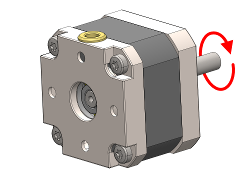](https://bookstack.vps-da8d40f3.arunmicro.com/uploads/images/gallery/2024-11/motor-direction-clockwise.png) |
| Negative | Counter-clockwise | [](https://bookstack.vps-da8d40f3.arunmicro.com/uploads/images/gallery/2024-11/motor-direction-anti-clockwise.png) |
The direction a mechanism moves in is not usually specified and depends on:
- The particular mechanism and its gearing
- Your perspective given the mounting orientation on the mechanism
You should therefore evaluate this in your application, and follow [these instructions](https://bookstack.vps-da8d40f3.arunmicro.com/link/27#bkmrk-note-regarding-rever) if required to flip motor direction so that positive and negative directions correspond as required.
### Stopping
Moves can be terminated at any time by stopping. There are several ways to stop:
| **Stop** | **Quick stop** | **Emergency stop** |
| Motor will decelerate to a stop using the current profile. | The deceleration profile is truncated as required to cause the motor to come to a full stop within 1 second.
The original profile is unmodified.
If the existing profile would bring the motor to a stop in under 1 second then that profile is used.
| Immediate full stop, and cut all electrical current to the motor. The motor is inert and unpowered.
The internal position counters become invalid because synchronicity is lost.
|
The stop and emergency stop commands can originate from within the SMD4 without external input:
- Emergency stop is raised when the SMD4 encounters a fault condition, see [here](https://bookstack.vps-da8d40f3.arunmicro.com/link/28#bkmrk-faults).
- During processes such as homing and closed loop control
### Encoders
Encoders allow the real mechanism position to be read, independent of position as determined by the step count. Encoders make closed loop control, in which the actual position and target position are continuously monitored and the corrections automatically made to minimise error, possible.
Supported encoders fall into two broad categories, incremental and absolute. Both are available in linear, angular and partial arc forms to suit different mechanisms. Both involve a scale and readhead.
The scale is typically a microscopically patterned thin metal strip affixed to the bed of the mechanism. The readhead is a small optical module attached to the carriage of the mechanism and reads the scale as it passes underneath. The scale is always sized such that the readhead can see it at any point within the physical travel of the mechanism.
[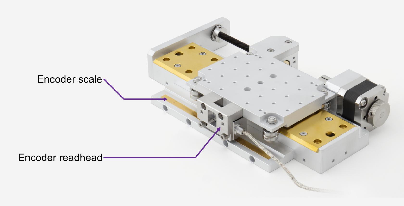](https://bookstack.vps-da8d40f3.arunmicro.com/uploads/images/gallery/2024-11/vsm23-x-ea-encoder-illustration.jpg)
#### Supported types
The SMD4 works with most incremental and absolute encoders meeting the requirements given [here](https://bookstack.vps-da8d40f3.arunmicro.com/link/26#bkmrk-copy-from-smd4-datas). Support for other encoder types may be added via firmware update, for example supporting word lengths other than 26 bits for absolute BiSS encoders; please contact us for details.
#### Incremental encoders overview
Incremental scales feature a repeating pattern. The readhead outputs quadrature A and B sine waves that encode the readhead position and direction as it passes over marks on the scale. These are passed to an interface external to the SMD4 which interpolates and outputs digital A and B quadrature signals. These signals drive a counter in the SMD4 encoder interface module which represents position.
[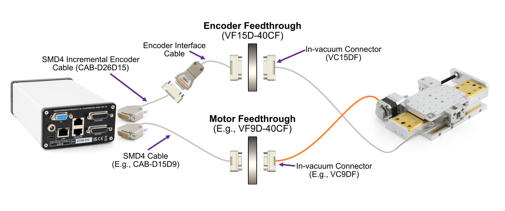](https://bookstack.vps-da8d40f3.arunmicro.com/uploads/images/gallery/2024-12/smd4-er-cabling-diagram.jpg)
The position is volatile and stored only in the counter on the SMD4, unlike in the case of the absolute encoder. The incremental encoder only provides pulses which are used to increment or decrement a counter according to direction of travel. If power is lost, the count is lost. If the mechanism is moved while powered off, there is no way to detect this.
An external interface sits between the encoder readhead and the SMD4. This is provided with the encoder supplied with the mechanism. These are specified with an interpolation factor, for example 20x. Incremental scales are specified with a pitch, for example 20 um. The interface interpolates this to increase the resolution, for example a 20x interface and 20 um pitch scale = 20 um / 20 = 1 um resolution.
Incremental encoders have several additional functions:
- P and Q limits - For linear scales, small magnets can be placed to mark limit points. The magnets are detected by the readhead and trigger a limit signal. Read the instructions for your mechanism to learn more.
- Error - An error signal is activated if for example, the readhead cannot read the scale properly.
- Z reference - Precision reference marks are placed on the scale. For angular scales, there is one mark, for linear scales there are multiple marks placed at fixed intervals, and the desired mark is selected by a small magnet placed next to it. When the readhead approaches the mark from either side, the Z signal is triggered. This can be used for establishing a datum position. Read the instructions for your mechanism to learn more.
The electrical interface requires these pins:
| **Name** | **Function** |
| A+ | Quadrature 'A' signal |
| A- |
| B+ | Quadrature 'B' signal |
| B- |
| Z+ | Quadrature 'Z' signal |
| Z- |
| P | Limits and error signals |
| Q |
| E |
| 0 V | Power |
| 5 V |
| ... For a total pin count of **11 pins** |
This generally requires a 15 way D-Sub feedthrough or similar. The pin count can be reduced to an absolute minimum of 6 pins, if the P, Q, E and Z signals are not required. The E signal is optional on the SMD4, and can be disabled/ignored if not required although this is not recommended.
#### Absolute encoders overview
Communication with the readhead is via a digital coms interface, and data are sent to the SMD4 from the readhead in packets verified by a CRC. The readhead connects directly to the SMD4 encoder interface module.
[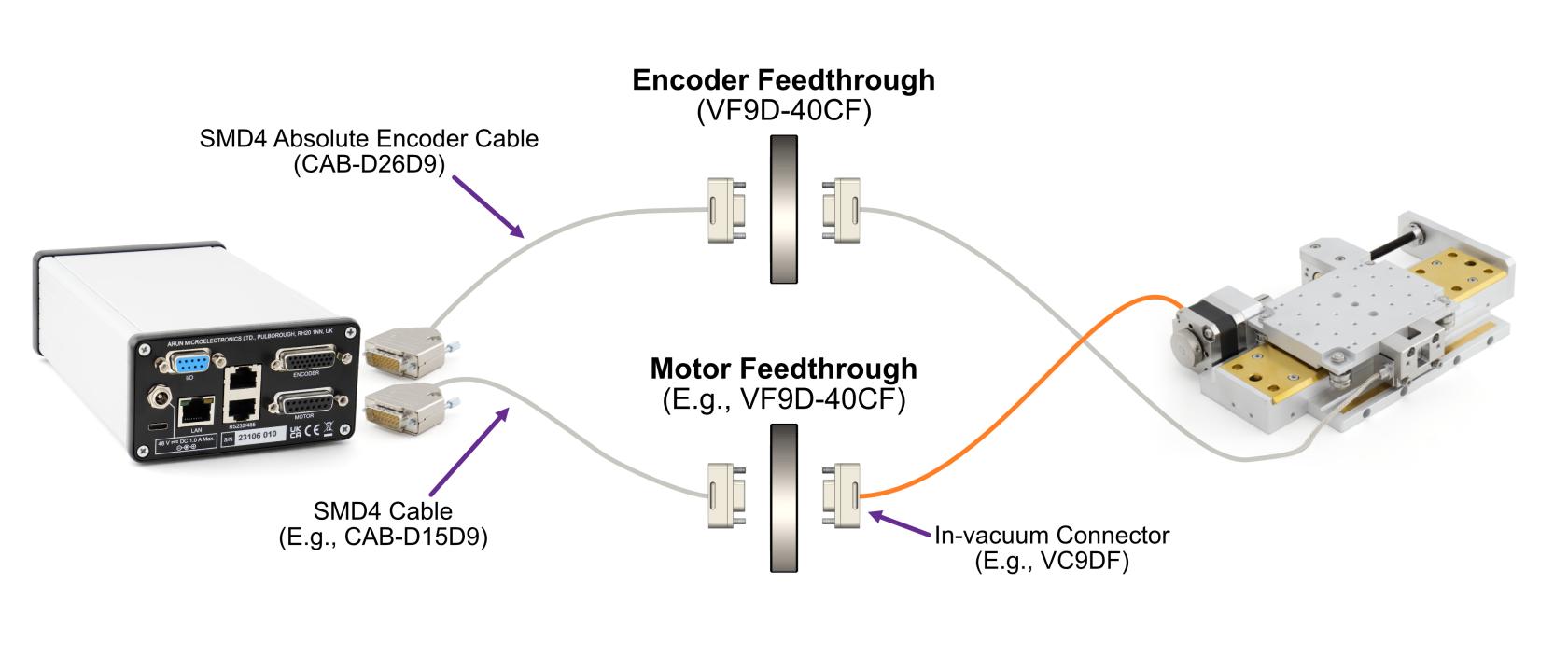](https://bookstack.vps-da8d40f3.arunmicro.com/uploads/images/gallery/2024-11/smd4-ea-cabling-diagram.jpg)
Absolute scales are patterned in such a way that the readhead can determine without any prior reference exactly where it is positioned, much like looking at a ruler. The absolute encoder therefore knows its absolute position at any time. The electronics can be powered off, the mechanism moved, and powered back on, and the readhead can still determine its absolute position.
Absolute encoders are specified by their resolution, for example 50 nm/count. The readhead outputs an absolute count value representing the position on the scale, from zero at one end, increasing toward the other end. The maximum count you will see for a given mechanism depends on the encoder resolution and scale length.
The scale cannot be positioned with micron level accuracy, so the zero count will not align with either end of the mechanism and there will always be a small offset. This also accounts for thermal effects, allowing extra scale at the ends of travel. For example, on a 50 mm linear stage, positioned at the negative extreme of travel might read a count of 46789, corresponding to a position of 50 nm x 46789 or 2.34 mm. Use the zeroing features of the SMD4 to set your own zero point.
Linear and partial arc scales start at zero and the maximum count depends on the length. For a 50 nm resolution system on a 50 mm scale the maximum count is at least 50e-3/50e-9 = 1e6. We can also infer from this that the maximum length scale for this 50 nm system with 26 bit BiSS is 50 nm \* 2^26 or about 3.3 m.
Angular (circular) scales count from zero to the maximum value then back to zero. For a 26 bit system, this means the count goes from 0 to 2^26 - 1 the next count on from 2^26 -1 is 0.
The scale is generally patterned at a much larger pitch than the published resolution, because the readhead uses interpolation techniques to obtain the published resolution.
The electrical interface requires these pins:
| **Name** | **Function** |
| MA+ | Clock |
| MA- |
| SLO+ | Data |
| SLO- |
| 0 V | Power |
| 5 V |
| ... For a total pin count of **6 pins** |
The much reduced pin count and simplicity of absolute encoders versus incremental makes them ideal for vacuum use. The overall system requires fewer components, less space, fewer feedthrough pins in addition to the advantages of having an absolute readout.
#### Handling of encoders
The SMD4 treats all encoder input as absolute. When an encoder is online and selected, the encoder is used to plan all movements. Moves you command are with respect to the encoder position, not the step counters. If any error occurs with the encoder in use, then a fault is triggered and the motor is disabled.
When an encoder is enabled, you can read speed and position data directly from it, as well as use it for functions such as closed loop control and virtual limits. These additional functions are discussed later.
It is essential that the encoder is correctly setup before use, otherwise unpredictable behaviour will result.
#### Special considerations for incremental encoders
Incremental encoders can in theory be treated as absolute provided that:
- An initial reference is established at first power on
- The save features of the SMD4 are utilised to save positions before power off
- The mechanism is never disturbed when the SMD4 is off
- Encoder operation is never interrupted
In practice, even if close attention is paid to these points, effects such as thermal expansion and contraction cannot be accounted for when powered off. As such, incremental encoders are usually used with a reference switch or other means to establish a fixed reference at power up if absolute position is important.
#### Special considerations for absolute angular encoders
To allow for more than one rotation to be tracked (recall that absolute angular encoder rings count from 0 to a maximum value, with the next count being 0) the SMD4 treats the absolute encoder in a pseudo incremental manner. This involves two counters, the 26 bit unsigned integer count from the readhead (readhead count), and a 64 bit signed counter maintained on the SMD4 (SMD4 count):
1. At startup, SMD4 count is set equal to readhead count
2. As the SMD4 runs, the readhead count is sampled rapidly, and the difference between this and the last readhead count is added to the SMD4 count
The properties of wraparound integer arithmetic ensure the proper behavior when the readhead counter crosses over the maximum count to zero, or vice versa, boundary.
This allows (at least during the power on time of the SMD4) multiple rotations to be tracked, and the availability of all encoder functions. For example, closed loop control could be used to home to a location of 100.5 revolutions, or virtual limits used to prevent a rotary mechanism from rotating too many times and tangling its leadout wires.
#### Setting up an encoder
Having connected the encoder and powered on follow these steps to manually configure an encoder. Values for settings required here can be found in the documentation supplied with your mechanism. This section assumes the drive is otherwise configured and working.
Alternatively, use the SMD4s built in presets functionality to automatically configure these settings to suit your mechanism, see [mechanism setup and presets](https://bookstack.vps-da8d40f3.arunmicro.com/link/28#bkmrk-mechanism-setup-and-).
| **Step** | **Details** |
| 1 | **Check encoder indicator lights**
| Check indicator light on encoder is on. There might be more than one light.
For Renishaw encoders shipped with AML mechanisms, provided the light or lights are on and any color other than red, you may proceed. A red light usually indicates a fault which should be fixed before proceeding. Refer to the documentation provided with the mechanism for more details.
|
| 2 | **Select the encoder** | Set encoder selection to incremental or absolute as required, and decide if the error signal should be used (incremental only) |
| 3 | **Set units** | Configure the units (degrees, meters etc. to suit your mechanism if not already done so).
It may be convenient to set a unit here that matches that in the mechanism documentation.
|
| 4 | **Set mechanism displacement per step** | This is the distance moved by the mechanism per step, usually referred to as the resolution in user documentation. |
| 5 | **Check mechanism direction** | Make one or more small moves and verify that directions are as you expect. If not, then see [here](https://bookstack.vps-da8d40f3.arunmicro.com/link/27#bkmrk-note-regarding-rever) to reverse motor direction. |
| 6 | **Set displacement per count** | This is the distance moved per encoder count. For example, for linear absolute encoders this might be 50 nm. If units are set to meters, you can simply enter 50e-9. |
| 7 | **Determine flip**
| The direction of the encoder scale must match that of the motor, i.e. when the motor moves in a positive, incrementing direction, the encoder must also.
A flip option allows the encoder to be virtually flipped to match the motor direction. An autoset feature is available; use this to automatically set flip as required. The motor will move a small distance to do this, and will return to its original position when complete.
|
| 8 | **Zero the encoder** | Position the mechanism at the desired zero point, either using the motor or by hand, then reset the absolute and relative counts as required. Finally use the save/store to device function to save your changes. |
### Closed loop control (Endpoint correction, EPC)
This feature uses an encoder to automatically minimise positioning errors. The SMD4 works continuously, monitoring position and adjusting the mechanism to your target position.
#### Introduction to closed loop control
Without an encoder, the SMD4 can only function in open loop mode. In open loop control, the SMD4 generates the required number of steps to perform the requested move and assumes that the motor moved the corresponding amount. There is no feedback to the SMD4 that the motor moved as expected. This approach works well with stepper motors because provided they maintain synchronicity fast accurate movements can be made without the need for feedback. This reduces cost, complexity and requires fewer components in vacuum.
In closed loop control, the SMD4 monitors the actual position of the mechanism via the encoder, and corrects for deviations when they occur.
#### How it works
Closed loop control on the SMD4 works using a method called Endpoint Correction, or EPC. In traditional closed loop control, actual and demand positions are continuously monitored, and a control algorithm adjusts motor movement to compensate out any errors. Proportional, integral and derivate gains are configured to obtain the desired system characteristics in terms of responsiveness, overshoot, undershoot and residual error.
EPC uses a different approach. A simple explanation, omitting some detail, is that every movement is initially made open loop. When the open loop move has completed, the actual and target positions are compared and position error determined. If the error falls below a user specified threshold, nothing more is done and the move is complete. If the error exceeds the threshold, a second move is made, again open loop, to try and eliminate the error. This process is iterative and continues either until the error has reduced below the threshold, or a specified maximum number of iterations of adjustment have occurred.
Once a move has completed, EPC continuously monitors position error and makes further adjustments if the error exceeds the threshold. In this way, EPC responds to events such as thermal effects or disturbance of the mechanism even when stopped.
Baseline error after each cycle of EPC is tracked, and cumulative error is considered for the next cycle.
EPC is optimised for vacuum use and allows closed loop control while minimizing temperature rise with little effort required by the user to configure it.
#### Configuration
##### Behavior
Defines what the feature should do:
- **None** – Feature is disabled/inactive
- **Warn** – Feature is enabled, and can raise a warning on alarm
- **Error** – Feature is enabled, and can raise an error on alarm
An alarm is the feature raising a notification. A notification is not necessarily an error, and the meaning is different for each feature. You can choose to route the alarm to a warning, or an error as described above by the behavior option.
Warnings are recorded but cleared automatically on the next successful move.
Errors are recorded and put the drive into a global fault state stopping the motor. An error must be cleared by the user to restore normal operation.
##### Maximum iterations
Maximum number of moves that EPC will make to correct position after the open loop positioning phase is completed. This can be set to a finite value or infinity, in which case the number of allowed moves is unlimited.
The moves count is zeroed at the start of each commanded move, and when a move successfully completes. If the mechanism is disturbed when stopped, a new cycle of corrections begins with the move count starting at zero once more.
##### Tolerance
When error reduces below this value, the move cycle is considered complete. The minimum value possible is half the mechanical resolution of the mechanism. Minimising tolerances results in more accurate positioning, at the expense of more adjustment and greater sensitivity to responding to disturbances. Larger tolerances result in less accurate positioning.
#### Alarm behaviour
An alarm is raised when:
- Maximum number of positioning iterations exceeded for this move
- The specified tolerance is impossible to meet given the mechanism resolution
### Range of motion limiter (Virtual limits, ROML)
Virtual limits are limits defined based on position.
When configured, range of motion is limited to the range specified. Demand position is adjusted if required to prevent the motor moving outside the specified range. For example, if a continuous rotation is demanded, and a virtual limit exists in that direction, your command is converted into a move to the virtual limit position. The motor will come to a stop at the limit using your specified profile.
If an encoder is present and the mechanism is forced outside the range of the virtual limit by an external means (for example, the mechanism is forced by hand) this is reported to the user.
This feature will work without an encoder, in which case the position is open loop and taken from the internal step counters.
#### Configuration
##### Behavior
As [here](https://bookstack.vps-da8d40f3.arunmicro.com/link/28#bkmrk-behavior).
##### Value one and two
These define the two virtual limits. There is no requirement for them to be in any particular order, for example value one might be 4 mm and value two -4 mm.
#### Alarm behaviour
Alarm is raised when:
- Movement outside the virtual limits is commanded (even though ROML will adjust the commanded move to prevent that happening)
- The mechanism is externally forced outside the limit range. This is only applicable to the encoder.
### Guard
This feature is like ROML, except that it does not adjust your input to prevent movement outside the specified range, and only warns or generates an error after movement outside the specified range has occurred.
This feature will work without an encoder, in which case the position is open loop and taken from the internal step counters.
#### Configuration
##### Behaviour
As [here](https://bookstack.vps-da8d40f3.arunmicro.com/link/28#bkmrk-behavior).
##### Value one and two
These define the two virtual limits. There is no requirement for them to be in any particular order, for example value one might be 4 mm and value two -4 mm.
#### Alarm behaviour
Alarm is raised when:
- Movement outside the virtual limits is commanded
- The mechanism is externally forced outside the limit range. This is only applicable to the encoder.
### Using the joystick
| The joystick is a two button controller on coiled lead that plugs into the front panel.
Use the right button for movement in the positive direction, and the left for movement in the negative direction. All moves occur according to the current profile in the drive.
It is available any time it is plugged in and enabled (see [operating modes](https://bookstack.vps-da8d40f3.arunmicro.com/link/28#bkmrk-operating-modes)), and has several modes of operation. It is a quick and easy way to simply move the mechanism without touching it. This can be useful during commissioning, or even as the primary means to control you mechanism.
| [](https://bookstack.vps-da8d40f3.arunmicro.com/uploads/images/gallery/2024-11/gpQimage.png)
|
| **Single** | Brief press to move one step, hold to move continuously, release button to stop |
| **Continuous** | Brief press to start moving continuously, subsequent press to stop |
| **Nudge** | Brief press to trigger a user defined relative move, called a nudge. Subsequent press stops |
#### Single
| **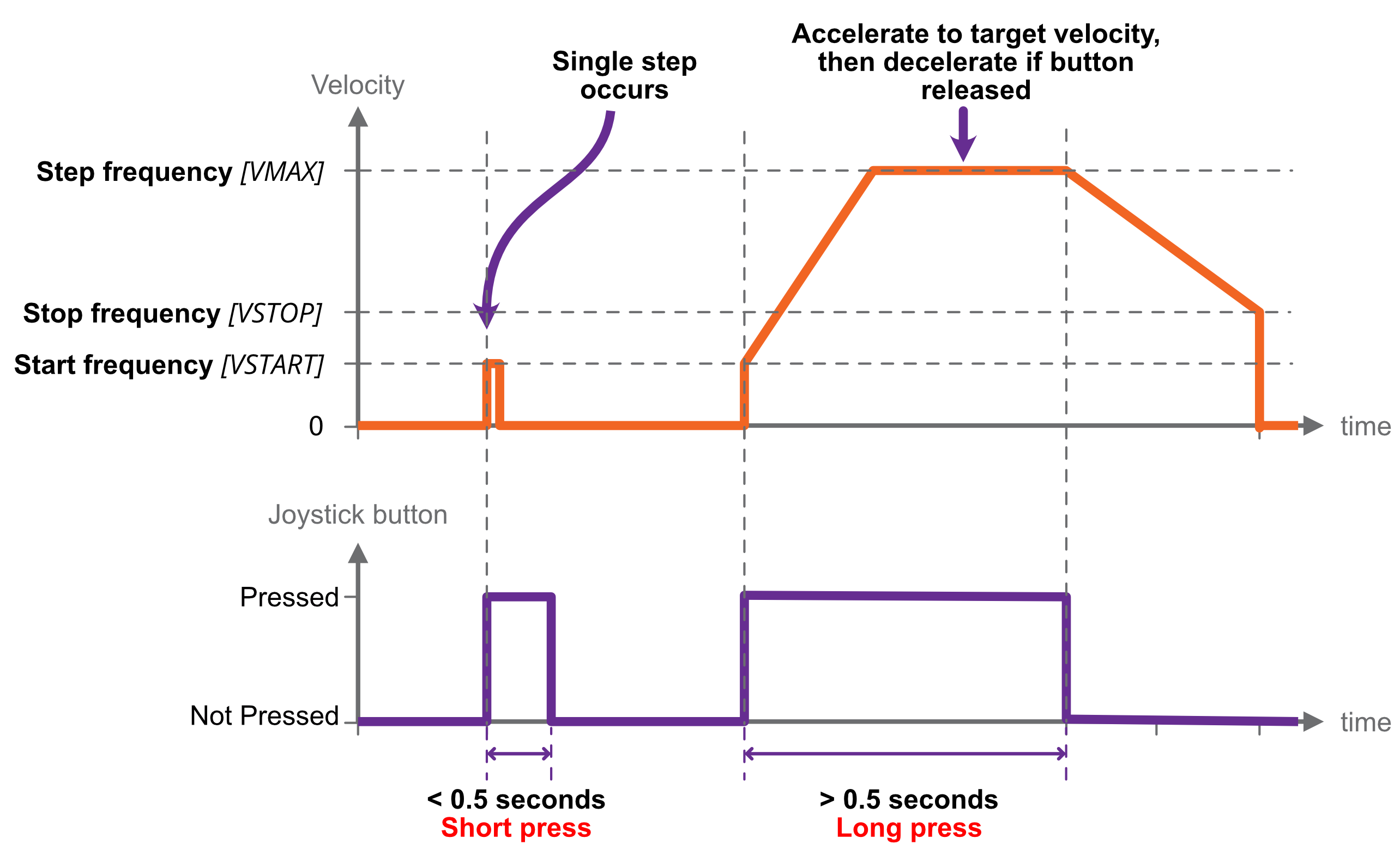**
| A short button press (< 0.5 s) causes a single step in the commanded direction. This is useful for precise positioning.
A long press (> 0.5 s) triggers acceleration toward the target frequency, while the button continues to be pressed.
Releasing the button causes the motor to decelerate toward a stop.
If the button is pressed while the motor is still decelerating, the motor once more accelerates toward target frequency for as
long as the button is held.
|
#### Continuous
| **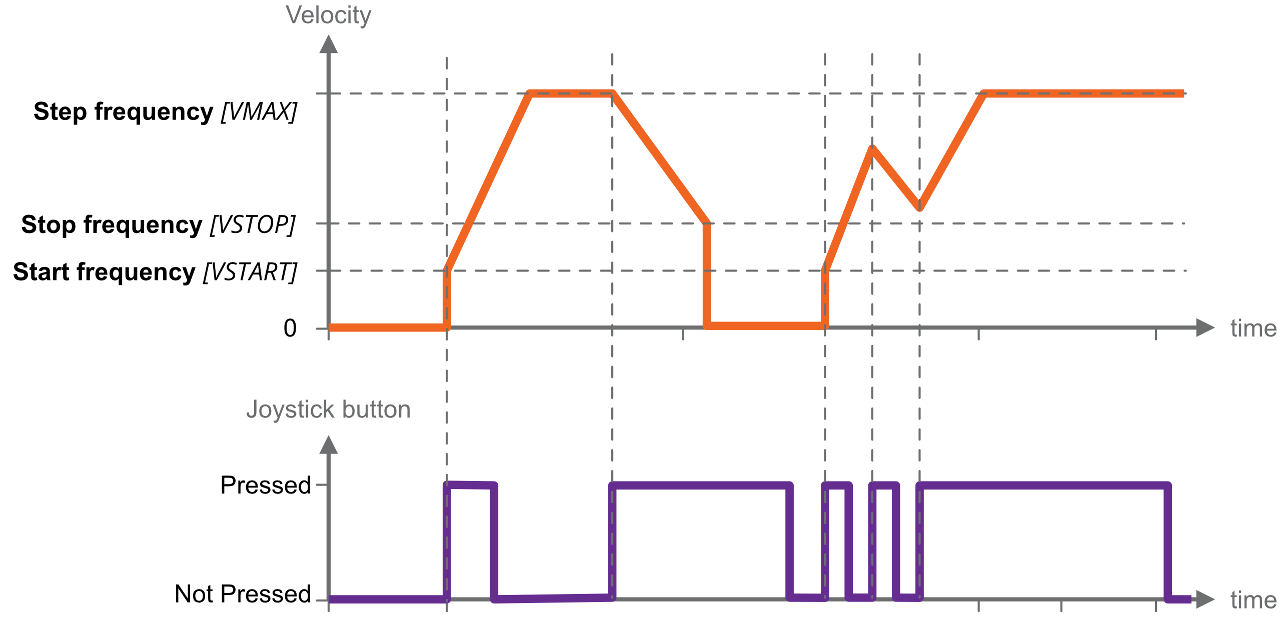**
| Motor accelerates toward target frequency on joystick key down. Continuing to hold the key down has no further effect.
On releasing and pressing the same key again, the motor decelerates toward a stop.
On pressing the alternate direction key, motor first decelerates to a stop before accelerating toward target frequency in the other direction.
If the motor has not yet come to a stop, and the same key is pressed again, the motor will once more accelerate towards target frequency, as illustrated left.
|
#### Nudge/Relative move
|
[](https://bookstack.vps-da8d40f3.arunmicro.com/uploads/images/gallery/2024-11/nudge-relative-move.png)
| Trigger a pre-defined relative move with the joystick.
You specify the distance, or nudge value, and trigger the move to start in the desired direction according to which joystick button is pressed.
On pressing a joystick button, a relative move of the specified distance and direction is made.
If any button is pressed while the move is in progress, the motor decelerates to a stop and the commanded move is not completed.
|
| The nudge value is signed, and the relative move performed is the product of the button and nudge value. The negative button multiplies the nudge value by -1, and the positive button +1. For example, if the nudge value is -100, and the negative joystick button is pressed, then the relative move made will be -100 \* -1 = 100.
|
### Homing to limit switches
Some mechanisms include one or more limit switches, positioned typically at the limits of travel or other reference position.
Homing is an automated procedure where the motor is driven to a chosen limit switch in a precise and repeatable manner. Most users then reset the position counters, and use that position as a reference going forward.
Homing only works with physical limit switches.
#### Homing cycle
You can choose to home in the positive or negative direction.
The motor first moves toward the limit switch using the existing movement profile. On the limit switch being triggered, the step frequency is halved, and the motor reversed until the limit switch is not triggered. Finally, the motor moves toward the limit switch at a step frequency of 30 Hz until the limit switch is triggered.
**INFORMATION:**
Limit switches are not latching, i.e. as soon as a limit input becomes not triggered, for example if the mechanism is able to first actuate a limit switch and then continue moving past it until the limit switch is no longer actuated, then the SMD4 will be unaware of this and will continue to drive the motor if commanded.
Limits switches and cams are normally arranged such that the limit switch is triggered from the desired point up to and including the point at which the mechanical limit of the mechanism is encountered.
### Step and direction interface
Motor movement is controlled by externally supplied step and direction signals. There are two sub modes, normal and triggered.
Set the mode to step and direction to use this function. Once in step direction mode, motor movement can only be controlled via the step direction interface, and not via other means such as the joystick or remote interface.
#### Normal mode
The SMD4 can be configured to step on the rising or rising and falling edges, which halves the step clock rate required.
The external enable fault is non-latching when in step direction mode; once the external enable state is restored, or the external enable setting is changed to false, normal operation will resume immediately without the need to clear it.
Steps are generated according to the current resolution. For example, with the edge setting on rising only, and microstep resolution set to 128, each rising edge on the step input will generate a single 1/128th step.
A step interpolation option is available; when enabled, the step input behaves as it would with the current resolution, except that each step input is interpolated to 256 microsteps. This is done by evaluating the rate at which steps arrive and timing 256 microsteps within the step-to-step period. This gives all the benefits of microstepping at high resolution while minimising the input clock rate.
The relationship between step input, resolution and actual step frequency is given below:
***Motor Step frequency \[Hz\] = (Step input \[Hz\] / Resolution)***
**INFORMATION:** Stopping on fractional steps
There is no mechanism to prevent the motor from stopping on fractional steps as there is in all other modes.
Stopping on fractional steps will result in the motor temperature rising much faster than it otherwise would and is generally not suitable for vacuum applications. Therefore, configure the external step generator to meet this criteria.
**INFORMATION:** Preparation before switching out of Step/Direction mode
When changing to another mode from Step/Direction mode, ensure that any movement being commanded via Step/Direction interface has completed, and that the motor is at a full step position before switching.
#### Triggered mode
This mode works the same as [joystick continuous mode](https://bookstack.vps-da8d40f3.arunmicro.com/link/28#bkmrk-joystick), except that the positive and negative inputs that would normally be supplied via the joystick input are instead generated from the step and direction inputs:
In the case of Step/Direction mode, it is the responsibility of the external controller to perform any final activities, such as coming to a stop, before changing the mode.
### Bake
Heats the motor by energising both phases and holding the motor stationary, regulating the current to achieve a set point temperature. Used to drive off adsorbed moisture in the motor.
Set the mode to bake to use this function.
Before engaging bake mode, set the target bake temperature. When in bake mode, the green status indicator will flash briefly at intervals as a reminder that this mode is active.
### Enable input
An enable input is present as part of the SDE interface, but the enable signal may be used in any mode. The motor is enabled when high and disabled (all motor movement inhibited) when low.
The enable input is ‘gated’ by an external enable setting; when enabled, the behaviour described above applies. When disabled, the enable input is treated as if it was true, regardless of the actual state. This allows the user to decide whether the enable input is used or not.
When the enable input is not used, then the SMD4 is responsible for enabling the motor as required, consistent with any other requirement described in this document.
### Limits
| Mechanisms sometimes include limit switches, typically mechanical switches positioned to open or close when some start or end point of travel is reached for example. This is used as a trigger to stop the motor
Configuration options allow limits to be individually or globally enabled or disabled, polarity to be set (i.e. trigger limit on switch open, called ‘Active low’ or switch closed, called ‘Active high’). The configuration options are illustrated below. AML Device control software additionally allows each limit to be given a custom name, for example ‘right switch’ to make it easier to identify within the software.
|
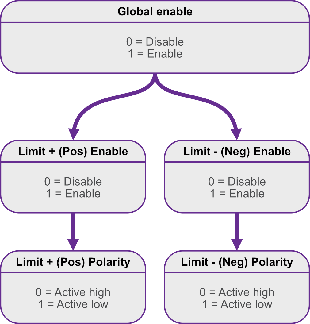
|
| Limit activation summary in relation to direction
| | | Limit + (Pos) triggered
| Limit - (Neg) triggered
| | Positive | Motor disabled | Motor enabled | | Negative | Motor enabled | Motor disabled |
|
| Limits are intended for use with the mechanical switches typically found in vacuum mechanisms, but other types of switch, for example, hall effect or optical limit switches can be interfaced. The high and low logic thresholds are 1.5 V and 0.55 V respectively. Limit inputs can withstand up to 12 V maximum. The limits input circuit is outlined below for reference. | 
|
### Faults
If a fault occurs, the motor is stopped and power to the motor is removed. The cause of the fault is indicated via the red front panel indicator, as shown below, and reflected in the error flags available via the remote interface.
#### Types of fault
| ****
| **Internal**
A hardware or software malfunction inside the SMD4. For example, user settings have become corrupted and failed to load properly.
|
| ****
| **External enable criteria not satisfied** The external enable setting is ‘true’ and the SMD4 requires the external enable signal to be high to enable the motor. Either supply an enable signal, or if you do not wish to use the enable input, disable the external enable setting by setting it to ‘false’, which tells the SMD4 to ignore the state of the enable signal.
|
| ****
| **Motor temperature**
Motor temperature has exceeded 190 °C or a fault has been detected with the temperature sensor. Excessive temperature can damage the insulation on the motor windings, and the SMD4 does not allow the motor to be driven. The SMD4 shuts down the motor before this can happen to prevent possible damage to the motor. Wait for the motor to cool before attempting to run the motor again.
**INFORMATION: **The motor is also disabled if the temperature sensor is misconnected or fault in order to protect the motor from possible damage to the insulation material.
|
|
| ****
| **Motor short**
A motor short has been detected. Motor phase-to-phase and phase-to-ground shorts can be detected by the SMD4. Inspect the motor and wiring to resolve before attempting to run the motor again.
|
| ****
| **Limit hit**
Indicator flashes briefly once a second. A limit has been triggered and has stopped the motor.
|
#### Clearing a fault
Faults may be cleared using the clear command, or by pulling the fault reset pin to the ‘GND’ pin the I/O connector.
The external enable fault is non-latching when in step direction mode; once the external enable state is restored, or the external enable setting is changed to false, normal operation will resume immediately without the need to clear it as described above.
# Software
### Installation and setup
The SMD4 is compatible with the AML Device Control software, which can be downloaded from the Software page on our website: [https://arunmicro.com/documents/software/](https://arunmicro.com/documents/software/)
- Connect all SMD4 devices to your computer If you intend to ultimately connect via LAN or Serial, start off by using the USB interface to perform basic setup on the LAN or serial interface first, then once satisfied connect on LAN or Serial as required.
Multiple instances of the same physical SMD4, but on different interfaces are allowed. For example, you could plug in the SMD4 with a network cable and USB lead, add the device connected via USB, configure network settings, then add device again as a network device. This can be useful during commissioning in establishing a working setup.
Note that the LAN interface only allows one connection at a time; auto-discovery of network connected device will fail to discover a device that is always connected to another software instance, be it AML Device Control or any other software.
- Start the AML Device Control software and click ‘Add device’ in the top left corner
[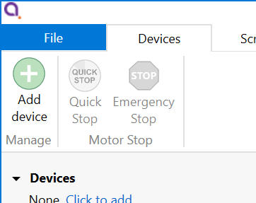](https://bookstack.vps-da8d40f3.arunmicro.com/uploads/images/gallery/2025-01/image.png)
Connected SMD4 devices should automatically appear in the list. Select all devices that you wish to add and click “Add n selected devices”
[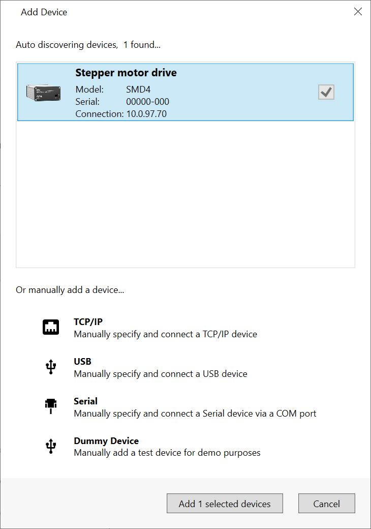](https://bookstack.vps-da8d40f3.arunmicro.com/uploads/images/gallery/2024-02/tVkimage.png)
The speed of auto detection varies by interface quantity of ports on your PC. Detection of USB and LAN devices is typically quick, whereas detection of devices connected via RS232 or RS485 can be considerably slower if a large number of COM ports are present on the PC.
The SMD4 network interface has an implementation of SSDP (Simple Service Discovery Protocol) which allows it to be discovered easily on a network, without knowing its IP address.
### Overview
The default layout of the software is shown below:
[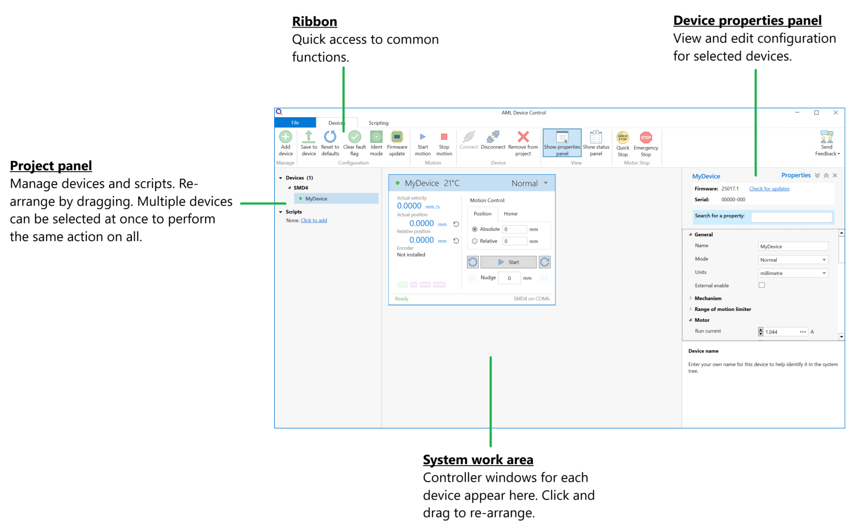](https://bookstack.vps-da8d40f3.arunmicro.com/uploads/images/gallery/2025-01/JMIimage.png)
#### **Project panel**
| Shows a list of the devices and scripts in the project. Currently selected devices are highlighted. Multiple devices can be selected by holding down CTRL and clicking. The device properties panel shows the properties for the selected device(s).
Right-clicking on an empty area within the project panel presents a context menu, with options to add new devices, new scripts or importing scripts.
|
|
[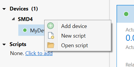](https://bookstack.vps-da8d40f3.arunmicro.com/uploads/images/gallery/2025-01/qWlimage.png)
|
|
|
|
|
| The right-click context menu on each device provides access to functions such as clearing faults or placing the selected device into ident mode in which the green status indicator flashes.
|
| [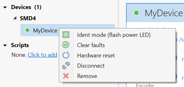](https://bookstack.vps-da8d40f3.arunmicro.com/uploads/images/gallery/2025-01/9A5image.png)
|
A status indicator next to each device shows the current status of each device according to these colours:
| Colour
| Description
|
| 
| Device connected and ready
|
| 
| Bake mode running, limit switch triggered or joystick connected
|
| 
| Device in a fault state
|
| 
| Device disconnected
|
#### **Device properties panel**
Select one or more devices in the project panel; their properties are displayed and can be edited here. A blank is shown for properties which are different across the selected devices. As each property is selected, help text appears at the bottom of the panel describing the configuration option in more detail.
- Some properties allow selection of one of several choices, for example, temperature sensor selection:

- Others such as ‘Run current’ simply require a numeric value to be entered
- Others allow values to be entered directly, or the three dots button to the right to be clicked. This opens a window, allowing a more complex value to be input, for example, ‘Acceleration’ allows input in the native units or seconds:
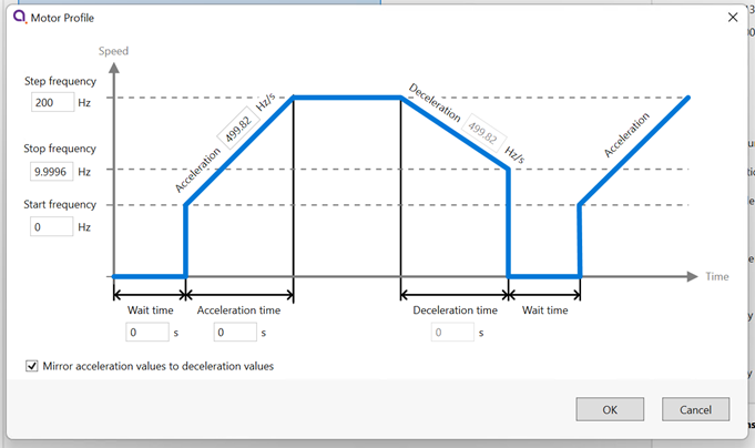
#### **System work area**
Controller windows for each device appear in this area. Windows can be arranged as desired and will automatically ‘snap’ to a grid making it easy to keep them neatly organised.
#### **Controller window**
| Shows a status summary for the selected device, providing essential information such as actual velocity, actual (absolute) position, relative position and error status.
Absolute and relative position may be reset using the  icons adjacent to the readouts.
Individual devices may be controlled using the buttons on the controller window, or if multiple devices are selected in the system tree on the left, use the controls on the ribbon to operate them all at once.
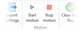
| [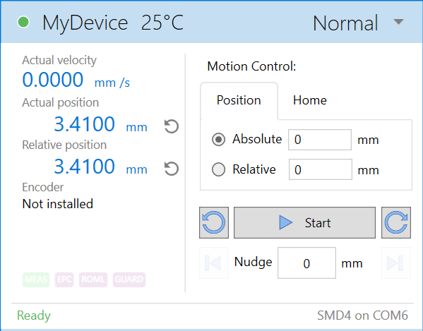](https://bookstack.vps-da8d40f3.arunmicro.com/uploads/images/gallery/2025-01/YJXimage.png)
|
Be aware that the synchronisation between multiple SMD4s is not specified or guaranteed. For example, if multiple devices are selected and the start button on the ribbon is clicked delays within the computer, software, and data connection to the SMD4 mean that each SMD4 will start or stop its motion at a slightly different moment, therefore this option is not suitable for performing complex co-ordinated movements across multiple axes.
#### Ribbon
Contains buttons for all actions. Hover over a button with the mouse to show tooltip with help information.
[](https://bookstack.vps-da8d40f3.arunmicro.com/uploads/images/gallery/2025-01/8ibimage.png)
### Scripting
| The software includes an easy to use script editor, that allows for sequences to be programmed and executed on multiple connected SMD4 devices, as well as system level operations such as adding and removing SMD4 devices from the project.The scripting language used is JavaScript; this is powerful, easy to use and extensively documented. A global ‘smd’ object is made available from which you perform all interactions with the SMD4s. Type ‘smd.’ (or use the 'CTRL+K' keyboard shortcut) and an auto completion popup appears, showing all available commands, as well as help documentation for each. Press the enter key to select an option, then provide any arguments required. | 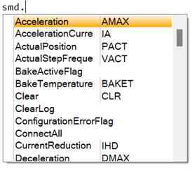
|
Information on the available SMD4 device specific commands can be found in section [USB](https://bookstack.vps-da8d40f3.arunmicro.com/link/50#bkmrk-usb) of this manual. Serial command mnemonics will be auto completed by the script editor. The arguments of each scripting function are identical to those shown in section [Command Reference](https://bookstack.vps-da8d40f3.arunmicro.com/books/smd4-user-manual/page/communications-protocol#bkmrk-command-reference), however, the format of querying and commanding is different. The example below shows how the SMD4 mode can be set and queried:
| smd.Mode(1);
smd.Mode();
| // Set the SMD4 mode to 1 (Normal)
// Query state of mode
|
The ribbon contains scripting specific buttons.

#### Utility functions
These utility functions don't translate to a command executed by the SMD4, and are used to perform tasks such as connecting devices, or creating delays in your program.
| Function
| Description
|
| Add
| bool **Add**(string **serial**)
Add a new device to the project.
Returns true if the device has been detected and added to the project.
serial:
Device serial number.
|
| ClearLog
| void **ClearLog**( )
Clear command line.
|
| ConnectAll
| void **ConnectAll**( )
Connect all devices in the project.
|
| Delayms
| void **Delayms**(int **value**)
Delay for a specified duration in milliseconds, before executing the next instruction.
value:
Minimum: 0
Maximum: 2^31 -1
|
| DelaySeconds
| void **DelaySeconds**(int **value**)
Delay for a specified duration in seconds, before executing the next instruction.
value:
Minimum: 0
Maximum: 2147483
|
| DisconnectAll
| void **DisconnectAll**( )
Disconnect all devices in the project.
|
| Log
| void **Log**(string **value**)
Print value to the command line.
|
| Name
| bool **Name**(string **serial**, string **name**)
Change name of the device.
Returns true if the device has been found and name changed.
serial:
Device serial number.
name:
Device new name.
|
| Remove
| bool **Remove**(string **serial**)
Remove a device from the project.
Returns true if the device has been detected and removed from the project.
serial:
Device serial number.
|
| RemoveAll
| void **RemoveAll**( )
Remove all devices from the project.
|
| Select
| bool **Select**(string\[ \] devices)
Returns true if all the requested devices have been selected.
devices:
Name of the device(s).
|
| SelectAll
| void **SelectAll**( )
Select all devices.
|
| SelectNone
| void **SelectNone**( )
Deselect all devices.
|
Functions that query the SMD4 and that are not also available as a remote command are listed below.
Note that these all return an array rather than a single value, with each array element corresponding to the data from one SMD4. Use the array index syntax to access the desired element. This applies regardless of the number of devices.
For example, if there is only one SMD4 connected, use BakeActiveFlag()\[0\] to get the state of the bake active flag for that device.
The order of the array elements matches the order in which the SMD4 devices are selected. For example, suppose the “X-axis”, “Y-axis” and “Z-axis” named devices were selected with the command “smd.Select(“Z-axis”, ”X-axis”, ”Y-axis)”, to check the standby flag of the “Z-axis” device, use MotorStandbyFlag()\[2\]. Notice that array indices are 0 based.
| Function
| Description
|
| BakeActiveFlag
| bool\[\] **BakeActiveFlag**()
Returns true if the bake mode is running.
|
| ConfigurationErrorFlag
| bool\[\] **ConfigurationErrorFlag**()
Returns true if the motor configuration is corrupt.
|
| EmergencyStopFlag
| bool\[\] **EmergencyStopFlag**()
Returns true if the motor is disabled by software.
|
| ExternalEnableFlag
| bool\[\] **ExternalEnableFlag**()
Returns true if the external enable input is high.
|
| ExternalInhibitFlag
| bool\[\] **ExternalInhibitFlag**()
Returns true if the external enable input is disabling the motor.
|
| IdentModeActiveFlag
| bool\[\] **IdentModeActiveFlag**()
Returns true if the ident mode is active.
|
| JoystickConnectedFlag
| bool\[\] **JoystickConnectedFlag**()
Returns true if the joystick is connected.
|
| LimitNegativeFlag
| bool\[\] **LimitNegativeFlag**()
Returns true if the negative limit is active.
|
| LimitPositiveFlag
| bool\[\] **LimitPositiveFlag**()
Returns true if the positive limit is active.
|
| MotorOverTemperatureFlag
| bool\[\] **MotorOverTemperatureFlag**()
Returns true if the motor temperature is greater than 190 °C.
|
| MotorShortFlag
| bool\[\] **MotorShortFlag**()
Returns true if a motor phase to phase or phase to ground short has been detected.
|
| MotorStandbyFlag
| bool\[\] **MotorStandbyFlag**()
Returns true if the motor is stationary.
|
| TargetVelocityReachedFlag
| bool\[\] **TargetVelocityReachedFlag**()
Returns true if the motor is at the target step frequency.
|
| TemperatureSensorOpenFlag
| bool\[\] **TemperatureSensorOpenFlag**()
Returns true if the selected temperature sensor is open circuit.
|
| TemperatureSensorShortedFlag
| bool\[\] **TemperatureSensorShortedFlag**()
Returns true if the selected temperature sensor is shorted (not applicable to thermocouple)
|
#### Example scripts
##### Add device, rename and set device properties
// Add device with serial number 20054-027
smd.Add("20054-027");
// Set name of device with serial number 20054-027 to MyDevice
smd.Name("20054-027","MyDevice");
// Select device with name MyDevice
smd.Select("MyDevice");
// Set the acceleration and deceleration rate in Hz/s
smd.Acceleration(100);
smd.Deceleration(100);
// Set the acceleration current
smd.AccelerationCurrent(1.044);
// Set the hold current
smd.HoldCurrent(0);
// Set the run current
smd.RunCurrent(0.5);
// Set the start frequency
smd.StartFrequency(10);
// Set the step frequency
smd.StepFrequency(1000);
// Set the frequency at which the drive transitions to full step
smd.MicrostepTransition(500);
// Set the micostep resolution
smd.Resolution(64);
##### Execute a series of movements, illustrating synchronous move commands
// Select device and set mode to remote
smd.Select("MyDevice");
smd.Mode(1);
// Move +100 steps, then -500 steps, and finally +100 steps
// "MoveRelative" executes synchronously, i.e. the motor must arrive at its destination position before the next line of code executes
smd.MoveRelative(500);
smd.MoveRelative(-500);
smd.MoveRelative(100);
// Log the finishing step position to the command line output area
smd.Log(smd.ActualPosition()[0]);
##### Execute movement on multiple drives, illustrating synchronous and asynchronous commands
// Select first device and start a movement
smd.Select("Device\_0");
smd.Mode(1);
smd.MoveRelativeAsync(10000); // Execution continues to the next line of code immediately, regardless of how long this move will
// requires to complete.
// Select second device and start a movement
smd.Select("Device\_1");
smd.Mode(2);
smd.MoveRelativeAsync(5000);
// Both motors are completing their moves at the same time.
##### Get value of actual position counter and log to command line
// Select device with name MyDevice
smd.Select("MyDevice");
// Store actual position in a variable
pact = smd.ActualPosition();
// Log result to command line
smd.Log(pact[0]);
##### Check if the motor is in standby
// Select device with name MyDevice
smd.Select("MyDevice");
// Store status flags in a variable
status = smd.StatusFlags();
// Log a specific bit status of the selected device to the command line
if(status[0] = status[0] & (0x1 << 6)){
smd.Log("Motor is in standby");
} else {
smd.Log("Motor is running");
}
# Remote interfaces
The SMD4 offers 3 communication interfaces, USB, Ethernet and Serial. The serial interface is dual mode, and can be configured for RS232 or RS485. Multiple interfaces can be connected and in use at the same time (AML Device Control software allows you to connect the same device on multiple interfaces at once which may be useful during network setup for example). All interfaces use a text-based communication protocol described in section [Communications protocol](https://bookstack.vps-da8d40f3.arunmicro.com/books/smd4-user-manual/page/communications-protocol).
This section may only be relevant if you are using terminal software or writing your own application. AML Device control software interacts with the SMD4 in the same way and requires no specialist knowledge to use. A C# API is also provided, allowing you to easily integrate communication with the SMD4 into your own C# .NET application. If you do not wish to use the API, refer to the [Communications protocol](https://bookstack.vps-da8d40f3.arunmicro.com/books/smd4-user-manual/page/communications-protocol) section which describes the commands available and their usage.
### USB
A reversible USB-C connector is provided.
The SMD4 appears as a virtual COM port on your PC, and will be assigned a designation such as "COM1". Each unique SMD4 that is connected to the PC will be assigned a new designation. Upon reconnecting a previously known SMD4, it will typically assume the same designation as when last used, however, this behaviour cannot be guaranteed.
The virtual COM port does not require any particular configuration to function correctly. Typical settings such as baud rate and parity are not applicable.
Most programming languages include easy built-in methods to read and write data to and from a COM port, for example, the SerialPort class in the System.IO.Ports namespace in C#, or pySerial in Python. Alternatively, use a terminal program such as Tera Term to manually type commands and see responses. Remember to set line termination which is a carriage return followed by line feed (in hexadecimal, 0x0D, 0x0A)
### Serial
A pair of RJ45 connectors are provided allowing multiple devices to be bussed together if required. This is discussed in section [RS232/RS485](https://bookstack.vps-da8d40f3.arunmicro.com/books/smd4-user-manual/page/installation#bkmrk-rs232%2F485). Do not confuse these connectors with the Ethernet connector.
The serial interface can be configured for RS232 or RS485.
If connecting to a PC, a serial port is required. Modern PCs seldom include RS232/485 ports, so typically a USB adapter or add-in card is required. This appears on the PC as one or more COM ports.
Unlike the virtual COM port provided via the USB interface, the COM port must be configured correctly:
- Baud to match that set on the SMD4
- 1 stop bit
- No parity
- No flow control
Thereafter, the same notes as for USB apply.
Configure the mode of operation (RS232 or RS485) before plugging a connector in. Do not make changes to the mode without first disconnecting both connectors. Undefined behaviour will result if the SMD4 is connected to an RS485 network when in RS232 mode or vice-versa.
### Ethernet
A standard 10/100M ethernet port is provided. It features Auto MDI-X so straight or crossover cable may be used.
The factory default setup enables DHCP, so under normal circumstances, this will assign the network configuration to the SMD4. Alternatively, use another interface, such as USB, to configure the ethernet port.
The SMD4 uses port 11312 for its text-based communication protocol. Only one connection at a time is supported, additional connections will be refused.
As with COM ports, most programming languages provide easy means to open a socket and communicate with network devices. Alternatively, use a terminal program such as PuTTY to manually type commands and see responses. See example PuTTY setup below; change IP address to suit your device.
[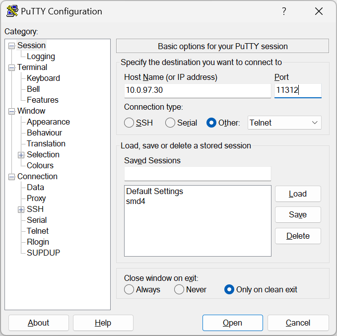](https://bookstack.vps-da8d40f3.arunmicro.com/uploads/images/gallery/2025-09/image.png)
#### SSDP
The SMD4 is discoverable on the network using SSDP (Simple Service Discovery Protocol). This makes it possible to plug the SMD4 into a network, then discover its IP address and so make a connection to it. Alternatively, use another interface, for example, USB to discover the network configuration.
Our AML Device Control software uses this mechanism to auto discover SMD4s on the network. Discovery may take some tens of seconds. If your device is not discovered, check that it has not already been connected to another instance of Device Control software running on your network, because the SMD4 only supports one connection at a time. Note however that you can ping the SMD4 at any time even if a connection is already established to verify its presence (for example, on Windows, use the "ping" command line tool). If the SMD4 can be pinged, but you are unable to connect to it using Device Control or your own software or terminal application, it is likely that the network interface is connected, perhaps to another instance of Device Control or other software.
##### Supported search targets (queries)
All – Not SMD4 specific, all devices on the network supporting this command will respond including SMD4
- "ssdp:all"
· UPNP Root Device, as above
- "upnp:rootdevice"
· Device – Specify domain name, device type and version to match the SMD4 and only SMD4s will respond:
- "urn:schemas-arunmicro-com:device:StepperMotorDrive:1"
- "urn:" SSDPR\_SCHEMA\_DOMAIN\_NAME ":device:" SSDPR\_SCHEMA\_DEVICE\_TYPE ":" SSDPR\_SCHEMA\_VER”
UUID – Specify a UUID and only one device having that UUID should respond. Use **this command** to get the UUID of your SMD4.
- "uuid:" UUID
Where:
- SSDPR\_SCHEMA\_DOMAIN\_NAME "schemas-arunmicro-com"
- SSDPR\_SCHEMA\_DEVICE\_TYPE "StepperMotorDrive"
- SSDPR\_SCHEMA\_VER "1"
##### Response
The SMD4 always responds in this way:
HTTP/1.1 200 OK\\r\\n
CACHE-CONTROL:max-age=120\\r\\n
DATE:\\r\\n
EXT:\\r\\n
LOCATION:http://10.0.97.6:80/desc.xml\\r\\n
SERVER:OS/version product/version\\r\\n
ST:uuid:28254095-7194-11ee-a857-44b7d0c76aa3\\r\\n
USN:uuid:28254095-7194-11ee-a857-44b7d0c76aa3::urn:schemas-arunmicro-com:device:StepperMotorDrive:1\\r\\n
\\r\\n
Note:
- Response always starts with http ok
- CACHE\_CONTROL, DATE and EXT are not used. CACHE-CONTROL has a default value but no meaning
- LOCATION is a URL to an xml file containing information as required by UPnP. The SMD4 does not implement a webserver to allow this file to be retrieved, however the root of the URL gives the IP address of the device which may be used to address future communications.
- SERVER:OS not implemented
- ST; this echos the search target sent in the query
- USN: gives the uuid and device type info
# Communications protocol
A simple text-based protocol is used. Commands are sent to the SMD4, checked and executed, and a response returned. Data are buffered on receipt and commands are evaluated and executed on a first in first out basis. Although not a requirement, it is usually easiest to send a command and evaluate the response before sending the next command.
Commands are in the form (Note that angle brackets are shown for clarity only, they are not part of the protocol):
`,,,…`
And responses are in the form:
`,,,,,…`
If the command executed successfully, or:
`,,,`
If the command failed to execute correctly.
Where:
### **Addressing**
This section is only applicable where multiple SMD4s are connected together on the same bus, using the serial interface in either RS232 or RS485 mode. The addressing logic described in this section works for all interfaces, but is redundant for USB and the network interface since those inherently implement addressing.
When multiple SMD4s exist on the same bus, a mechanism is required to allow them to be addressed uniquely or as a group. Likewise, only one device must use the bus at a time otherwise bus contention results when more than one device tries to drive the bus at a time.
This is accomplished via the address prefix, which is the at '@' symbol followed by a numeric address:
- 0 = Broadcast address, all SMD4s execute the command, but no response is sent
- 1 to 247 = Valid secondary address range. The addressed SMD4 executes the command and returns a response
- Any address outside this range is invalid, and the packet is silently ignored
Upon receipt of the first complete packet with an address prefix, the SMD4 enters addressing mode, and behaviour then changes as follows, until restart.
- Malformed packets are silently ignored. This includes any packet that does not include the addressing prefix but that is otherwise valid.
- Broadcast packets are silently parsed and executed. A response is not sent, and as such it cannot be determined whether the command executed successfully without submitting a further query addressed directly to the target SMD4.
- Packets that are otherwise correctly formed but having a target address that does not match that of the SMD4 are silently ignored.
### **Comma separation**
All elements are comma-separated, except for the message terminator which immediately follows the last item. A response is always sent on receipt of a message terminator except where addressing criteria are not met. If an argument was supplied with a command, for example, to set a value, the value set will be returned in the response and serves as an additional confirmation of the command having executed as expected.
Many commands accept a real number argument when the underlying quantity is an integer, or finite set of real numbers. In this case, the supplied value being otherwise acceptable is rounded to the closest integer or real number from the allowed set, and it is this value that is returned in the response.
**No data items to return**
If there are no data items as part of a response, only the SFLAGS and EFLAGS are returned. If an error occurred, then this will be reflected in the EFLAGS.
### Data types
The SMD4 uses the following data types. Arguments sent to and from the SMD4 will be one of these types. Bracketed values are notes or converted values and not part of the data sent to or from the SMD4. Same applies to quotes.
### Flags
Flags are reported by the device in hexadecimal format as explained above. E.g. a value of 0x0002 means bit 1 is set. The value of reserved flags is undefined and no particular value should be assumed.
#### Error flags (EFLAGS)
These indicate error conditions and are latching (i.e. remain set even after the error condition that caused them no longer persists). Reset the fault using the clear command, or the reset fault input. The motor is disabled if one or more error flags are set.
#### Status flags (SFLAGS)
#### Error codes
### Quick reference
#### Bake
#### Boost
#### Coms
#### Encoder
#### Limit inputs
#### Motion control
#### Motor
#### General
### Command reference
In the examples red text is data transmitted to the SMD4, and blue text is data received from the SMD4. // Green text preceded by a double forward slash is a comment relating to that data. Arguments where present are given as an argument name in angle brackets.
#### Bake
##### BAKE:RUN – Start bake
Start bake. Configure the bake temperature setpoint using [BakeTemperature](https://bookstack.vps-da8d40f3.arunmicro.com/link/51#bkmrk-baket-%E2%80%93-bake-tempera).
| Command: | **BAKE:RUN**<CR><LF> |
**Examples**
| BAKE:RUN<CR><LF>
0x0000,0x0000<CR><LF>
| // Run bake
|
##### BAKE:ELAPSED – Elapsed bake time
Gets the elapsed bake time.
| Query: | **BAKE:ELAPSED**<CR><LF>
|
| Response: | <duration>
|
|
|
| **Data** | **Type** | **Description
|
| duration | STRING | Elapsed time in format h:mm:ss, where h is hours, m minutes and s seconds.
|
| Tx: BAKE:ELAPSED<CR><LF>
Rx: 0x0000,0x0000,2:34:12<CR><LF>
| // Bake has run for 2 hours 34 minutes and 12 seconds
|
##### BAKE:T – Bake temperature setpoint
Gets or sets the bake temperature setpoint. To run bake, select bake mode using the [MODE,](https://bookstack.vps-da8d40f3.arunmicro.com/link/51#bkmrk-mode---choose-mode-o) then start bake using the run bake command. Use stop command to end bake.
| Command: | **BAKE:T,**<setpoint><CR><LF>
|
| Query: | **BAKE:T <CR><LF>
|
| Response: | <setpoint>
|
|
|
| **Data** | **Type** | **Description
|
| setpoint | UINT | \[Default: 150 °C\]
Min. 0 °C
Max. 200 °C
|
**Examples**
| BAKE:T,100<CR><LF>
0x0000,0x0000,100<CR><LF>
BAKE:T<CR><LF>
0x0000,0x0000,100<CR><LF>
| // Set bake setpoint to 100 °C
// Query
|
#### Boost
##### BOOST:EN – Boost enable
Gets or sets a value indicating whether the boost supply should be enabled. The boost supply steps up the input voltage from 48 V to 67 V to maximise motor dynamic performance. Enable for best performance. Regardless of this setting, the boost supply is disabled when input voltage falls below 48 V, and or the boost disable jumper is fitted.
| Command: | **BOOST:EN,**<state><CR><LF>
|
| Query: | **BOOST:EN <CR><LF>
|
| Response: | <state> |
|
|
| **Data** | **Type** | **Description** |
| state | BOOL | 0: Disable
\[1: Enable\]
|
**Examples**
| BOOST:EN,1<CR><LF>
0x0000,0x0000,1<CR><LF>
BOOST:EN<CR><LF>
0x0000,0x0000,1<CR><LF>
| // Enable boost
// Query
|
##### BOOST:JUMPER – Boost disable PCB jumper
Gets a value indicating whether the boost supply disable jumper is fitted. If the jumper is fitted, the boost supply is disabled and the maximum voltage supplied to the motor will equal the input voltage to the SMD4. This will compromise motor dynamic performance.
| Query: | **BOOST:JUMPER <CR><LF>
|
| Response: | <state> |
|
|
| **Data** | **Type** | **Description** |
| state | BOOL | 0: Jumper is not fitted, boost supply is enabled provided input voltage criteria met
1: Jumper is fitted, boost supply is disabled
|
#### Coms: Network
##### COMS:NET:DHCP – DHCP
Gets or sets a value indicating whether DHCP is enabled. If enabled, DHCP (Dynamic Host Configuration Protocol) will be used to automatically assign network configuration, such as IP address and gateway, to the device.
| Command: | **COMS:NET:DHCP,**<state><CR><LF>
|
| Query: | **COMS:NET:DHCP**<CR><LF>
|
| Response: | <state> |
|
|
| **Data** | **Type** | **Description** |
| state | BOOL | 0: Disable
\[1: Enable\]
|
**Examples**
| COMS:NET:DHCP,1<CR><LF>
0x0000,0x0000,1<CR><LF>
COMS:NET:DHCP<CR><LF>
0x0000,0x0000,1<CR><LF>
| // Enable DHCP
// Query
|
##### COMS:NET:GATEWAY – Gateway
Gets or sets the gateway address. When DHCP is enabled, the value read back will be the value assigned by DHCP rather than any value you might have set. Any value set however is retained, and will apply if DHCP is disabled at a later time.
| Command: | **COMS:NET:GATEWAY,**<address><CR><LF>
|
| Query: | **COMS:NET:GATEWAY**<CR><LF>
|
| Response: | <address> |
|
|
| **Data** | **Type** | **Description** |
| address | DOTTED DECIMAL | Gateway address |
**Examples**
| COMS:NET:DHCP<CR><LF>
0x0000,0x0000,1<CR><LF>
COMS:NET:GATEWAY,192.168.1.1<CR><LF>
0x0000,0x0000,10.0.96.1<CR><LF>
COMS:NET:DHCP,0<CR><LF>
0x0000,0x0000,0<CR><LF>
COMS:NET:GATEWAY<CR><LF>
0x0000,0x0000,192.168.1.1<CR><LF>
| // Query DHCP state and find that it's enabled
// Set the gateway; the returned value is that assigned by DHCP // not the value we just set
// Turn DHCP off
// Query gateway again
// Now DHCP is off, our assigned gateway value is used
|
##### COMS:NET:IP – IP Address
Gets or sets the IP address. When DHCP is enabled, the value read back will be the value assigned by DHCP rather than any value you might have set. Any value set however is retained, and will apply if DHCP is disabled at a later time.
| Command: | **COMS:NET:IP,**<address><CR><LF>
|
| Query: | **COMS:NET:IP**<CR><LF>
|
| Response: | <address> |
|
|
| **Data** | **Type** | **Description** |
| address | DOTTED DECIMAL | IP address |
**Examples**
| Tx: COMS:NET:IP<CR><LF>
Rx: 0x0000,0x0000,10.0.97.70<CR><LF>
| // Query the IP address
|
##### COMS:NET:IPCONF – Get network config summary
Outputs a summary of network configuration in human readable form.
| Query: | **COMS:NET:IPCONF**<CR><LF>
|
| Response: | <summary> |
|
|
| **Data** | **Type** | **Description** |
| summary | STRING | ASCII table summarizing the network configuration, see example. |
**Examples**
| Tx: COMS:NET:IPCONF<CR><LF>
Rx: 0x0000,0x0000,<CR><LF>
Ethernet interface:<CR><LF>
IPv4 Address. . . . . . . . . . . :10.0.97.70<CR><LF>
Subnet Mask . . . . . . . . . . .:255.255.248.0<CR><LF>
Default Gateway . . . . . . . :10.0.96.1<CR><LF>
DHCP State. . . . . . . . . . . . :Enabled<CR><LF>
| |
##### COMS:NET:LINK – Get link up status
Gets a value indicating whether the ethernet interface link is up. This will read back as false when the LAN connector is unplugged for example.
| Query: | **COMS:NET:LINK**<CR><LF>
|
| Response: | <state> |
|
|
| **Data** | **Type** | **Description** |
| state | BOOL | 0: Link down
1: Link up
|
**Examples**
| Tx: COMS:NET:LINK<CR><LF>
Rx: 0x0000,0x0000,1<CR><LF>
| // Query
// Link is up
|
##### COMS:NET:MAC – Get MAC address
Gets the Ethernet interface MAC address.
| Query: | **COMS:NET:MAC**<CR><LF>
|
| Response: | <mac> |
|
|
| **Data** | **Type** | **Description** |
| mac | MAC | MAC address, 12 hexadecimal characters grouped into pairs separated by a colon, for example "44:b7:d0:c7:16:75"
|
**Examples**
| Tx: COMS:NET:MAC<CR><LF>
Rx: 0x0000,0x0000,44:b7:d0:c7:16:75<CR><LF>
| // Query
|
##### COMS:NET:NETMASK – Subnet mask
Gets or sets the subnet mask. When DHCP is enabled, the value read back will be the value assigned by DHCP rather than any value you might have set. Any value set however is retained, and will apply if DHCP is disabled at a later time.
| Command: | **COMS:NET:NETMASK,**<mask><CR><LF>
|
| Query: | **COMS:NET:NETMASK**<CR><LF>
|
| Response: | <mask> |
|
|
| **Data** | **Type** | **Description** |
| mask | DOTTED DECIMAL | Mask |
| COMS:NET:NETMASK<CR><LF>
0x0000,0x0000,255.255.248.0<CR><LF>
| // Query
|
#### Coms: Serial
##### COMS:SERIAL:BAUD – Baud rate
Gets or sets the baud rate.
| Command: | **COMS:SERIAL:BAUD,**<baud>**<CR><LF>** |
| Query: | **COMS:SERIAL:BAUD**<CR><LF>
|
| Response: | <baud>
|
|
|
| **Data** | **Type** | **Description
|
| baud | UINT | Baud rate:
4800
9600
14400
19200
38400
57600
\[115200\]
230400
460800
921600
|
**Examples**
| COMS:SERIAL:BAUD,9600<CR><LF>
0x0000,0x0000,9600<CR><LF>
COMS:SERIAL:BAUD<CR><LF>
0x0000,0x0000,9600<CR><LF>
| // Set 9600 baud
// Query
|
##### COMS:SERIAL:MODE – RS232/RS485 mode selection
Gets or sets the serial coms mode, either RS232 or RS485. Unplug from the host device before changing the mode.
| Command: | **COMS:SERIAL:MODE,**<mode><CR><LF> |
| Query: | **COMS:SERIAL:MODE**<CR><LF>
|
| Response: | <mode>
|
|
|
| **Data** | **Type** | **Description
|
| mode | UINT | 0: RS232
\[1: RS485\]
|
**Examples**
| COMS:SERIAL:MODE,1<CR><LF>
0x0000,0x0000,1<CR><LF>
COMS:SERIAL:MODE<CR><LF>
0x0000,0x0000,1<CR><LF>
| // Set RS485 mode
// Query
|
##### COMS:SERIAL:RS485DEL – Turnaround delay
Gets or sets a value in milliseconds specifying the delay to execute between receipt of a command from the host and the client (SMD4) sending the response. Applicable to RS485 mode only.
The RS485 interface is half duplex (it can send or receive data, but cannot do both at once) and so by default is in the receive state. The interface switches to transmit mode when a command has been received, executed and a response is ready to send. The turnaround delay is used to insert an additional delay following execution of the command but preceding switching to transmit, to allow the host more time to switch into receive mode.
Experiment with increasing this setting if you find that host receives a response with a portion missing from the start of the response, for example missing some or all of the status an error flags.
| Command: | **COMS:SERIAL:RS485DEL,**<delay><CR><LF> |
| Query: | **COMS:SERIAL:RS485DEL**<CR><LF>
|
| Response: | <delay>
|
|
|
| **Data** | **Type** | **Description
|
| delay | UINT | Delay in milliseconds.
Default: 0
Minimum: 0
Maximum: 1000
|
**Examples**
| COMS:SERIAL:RS485DEL,10<CR><LF>
0x0000,0x0000,1<CR><LF>
COMS:SERIAL:RS485DEL<CR><LF>
0x0000,0x0000,10<CR><LF>
| // Set delay of 10 ms
// Query
|
##### COMS:SERIAL:SLAVEADDR – Slave address
Gets or sets the slave address. Only applicable when addressing mode is used, see [addressing section](https://bookstack.vps-da8d40f3.arunmicro.com/link/51#bkmrk-addressing).
| Command: | **COMS:SERIAL:SLAVEADDR,**<address><CR><LF> |
| Query: | **COMS:SERIAL:SLAVEADDR**<CR><LF>
|
| Response: | <address>
|
|
|
| **Data** | **Type** | **Description
|
| address | UINT | Slave address.
Default: 1
Minimum: 1
Maximum: 247
|
**Examples**
| Tx: COMS:SERIAL:SLAVEADDR,1<CR><LF>
Rx: 0x0000,0x0000,1<CR><LF>
Tx: COMS:SERIAL:SLAVEADDR<CR><LF>
Rx: 0x0000,0x0000,1<CR><LF>
| // Disable termination
// Query
|
##### COMS:SERIAL:TERM – Termination
Gets or sets a value indicating whether RS485 line termination should be used. If enabled, a 120 termination resistance is placed between the RS485 A and B pins. See [section on termination](https://bookstack.vps-da8d40f3.arunmicro.com/link/27#bkmrk-rs232%2F485).
| Command: | **COMS:SERIAL:TERM,**<state><CR><LF>
|
| Query: | **COMS:SERIAL:TERM**<CR><LF>
|
| Response: | <state> |
|
|
| **Data** | **Type** | **Description** |
| state | BOOL | 0: Disable
\[1: Enable\]
|
**Examples**
| COMS:SERIAL:TERM,0<CR><LF>
0x0000,0x0000,0<CR><LF>
COMS:SERIAL:TERM<CR><LF>
0x0000,0x0000,0<CR><LF>
| // Disable termination
// Query
|
#### Encoder
##### ENC:BSN – Board serial number
Gets the encoder board serial number. If the encoder module is not present an empty string is returned.
| Query: | **ENC:BSN**<CR><LF>
|
| Response: | <serial> |
|
|
| **Data** | **Type** | **Description** |
| serial | STRING | Encoder board serial number.
|
**Examples**
| ENC:BSN<CR><LF>
0x0000,0x0000,1232492<CR><LF>
| // Query
|
##### ENC:DAT – Encoder readout
Gets the latest data from the encoder. If the encoder module is not present, all values read as zero. Data relating to a particular type of encoder (incremental, or BiSS absolute) are only applicable when that type of encoder connected and otherwise are of undefined value.
| Query: | **ENC:DAT**<CR><LF>
|
| Response: | <flags>,<incremental ab count>,<incremental z count>,<absolute count>,<absolute position>,<absolute velocity>,<relative position>,<relative velocity> |
|
|
| **Data** | **Type** | **Description** |
| flags | UINT | Encoder status flags. 16 bit value presented as an unsigned integer. The bits are:
Bit Description
0: Incremental P limit signal
1: Incremental Q limit signal
2: Incremental E (error) signal
3: BiSS CRC error
4: BiSS warning
5: BiSS error
6: reserved 6
7: reserved 7
8: Installed
9: Online
10: reserved 10
11: reserved 11
12: reserved 12
13: reserved 13
14: reserved 14
15: reserved 15
|
| incremental ab count | INT | Incremental encoder AB (position) count.
|
| incremental z count | UINT | Incremental encoder Z (reference marker) count. The value increments once per transition, which means that the counter will increment by 2 if it passes cleanly over the reference mark in either direction.
|
| absolute count | INT | Absolute encoder count
|
| absolute position | FLOAT | Absolute position determined from the encoder. If the encoder is incremental then then the value is pseudo-absolute as explained <here>.
|
| absolute velocity | FLOAT | Absolute velocity determined from the encoder
|
| relative position | FLOAT | Relative position determined from the encoder.
|
| relative velocity | FLOAT | Relative velocity determined from the encoder.
|
**Examples**
| ENC:DAT<CR><LF>
0x88c6,0x0000,888,7708795,128,0,5.00371093750000E+01,0.00000000000000E+00,5.00371093750000E+01,0.00000000000000E+00<CR><LF>
| // Query
|
##### ENC:DPC – Displacement per count
Get or set the displacement per count, i.e. the distance represented by one encoder count.
| Command: | **ENC:DPC,**<dpc><CR><LF>
|
| Query: | **ENC:DPC**<CR><LF>
|
| Response: | <dpc> |
|
|
| **Data** | **Type** | **Description** |
| dpc | FLOAT | Displacement per count.
|
**Examples**
| ENC:DPC<CR><LF>
0x0000,0x0000,50E-09<CR><LF>
| // The displacement per count is 50e-9. If this were a linear encoder and the units were meters, then this would mean 50 nm.
|
##### ENC:FLIP – Flip
Gets or sets a value indicating whether the encoder readout should be flipped/inverted, such that positive is negative and vice versa. This is done internally by multiplying the encoder count by 1 when flip is disabled, and -1 when flip is enabled, and is applied as the last processing step (i.e. after offsets and other adjustments have been applied).
| Command: | **ENC:FLIP,**<state><CR><LF>
|
| Query: | **ENC:FLIP**<CR><LF>
|
| Response: | <state> |
|
|
| **Data** | **Type** | **Description** |
| state | BOOL | \[0: Disable\]
1: Enable
|
**Examples**
| ENC:FLIP<CR><LF>
0x0000,0x0000,0<CR><LF>
| // Flip is disabled
|
##### ENC:FLIP:AUTOSET - Autoset flip
Starts a process that automatically determines the correct flip setting. This takes a few seconds and is done by moving the motor a small amount, checking the resulting encoder displacement and then changing the flip setting if required. The motor is moved back to its initial position when the process completed.
| Command: | **ENC:FLIP:AUTOSET**<CR><LF>
|
| Response: | |
**Examples**
| ENC:FLIP:AUTOSET<CR><LF>
0x0000,0x0000<CR><LF>
| // Autoset flip ran successfully
|
##### ENC:FW - Firmware version
Gets the encoder module firmware version.
| Query: | **ENC:FW**<CR><LF>
|
| Response: | <version> |
|
|
| **Data** | **Type** | **Description** |
| version | STRING | Encoder firmware version
|
**Examples**
| ENC:FW<CR><LF>
0x0886,0x0000,24285.79<CR><LF>
| // Firmware version is 24285.79
|
##### ENC:INC:LIMITS:EN - Incremental PQ limits enable
Gets or sets a value indicating whether incremental PQ limits should be enabled. PQ limits can be configured as desired with the other related settings, and this option used to enable or disable them.
| Command: | **ENC:INC:LIMITS:EN,**<state><CR><LF>
|
| Query: | **ENC:INC:LIMITS:EN**<CR><LF>
|
| Response: | <state> |
|
|
| **Data** | **Type** | **Description** |
| state | BOOL | \[0: Disable\]
1: Enable
|
##### ENC:INC:LIMITS:P:EN - Incremental P limit enable
Gets or sets a value indicating whether incremental P limit should be enabled.
| Command: | **ENC:INC:LIMITS:P:EN,**<state><CR><LF>
|
| Query: | **ENC:INC:LIMITS:P:EN**<CR><LF>
|
| Response: | <state> |
|
|
| **Data** | **Type** | **Description** |
| state | BOOL | \[0: Disable\]
1: Enable
|
##### ENC:INC:LIMITS:Q:EN - Incremental Q limit enable
Gets or sets a value indicating whether incremental Q limit should be enabled.
| Command: | **ENC:INC:LIMITS:Q:EN,**<state><CR><LF>
|
| Query: | **ENC:INC:LIMITS:Q:EN**<CR><LF>
|
| Response: | <state> |
|
|
| **Data** | **Type** | **Description** |
| state | BOOL | \[0: Disable\]
1: Enable
|
##### ENC:INC:LIMITS:STOPMODE - Incremental PQ limits stop mode
Gets or sets the incremental PQ limits stop mode.
| Command: | **ENC:INC:LIMITS:STOPMODE,**<mode><CR><LF>
|
| Query: | **ENC:INC:LIMITS:STOPMODE**<CR><LF>
|
| Response: | <mode> |
|
|
| **Data** | **Type** | **Description** |
| mode | UINT | \[0: Hard stop; the motor will stop immediately on a limit being triggered\]
1: Soft stop; the motor decelerates according to the profile
|
**Remarks**
When using hard stop, keep in mind that steps may be lost depending on the slewing speed and load on the motor. Treat position counters with caution until the true position has been established. Conversely, when using soft stop, ensure that the motor can decelerate to a stop before the physical end of travel is reached and steps are lost.
##### ENC:INC:LIMITS:SWAP - Incremental PQ limits swap
Gets or sets a value indicating whether the P and Q limits should be swapped. The standard configuration is for the P limit to be positioned at the end of the scale reached by the encoder count incrementing, and the Q limit the end of the scale reached by the encoder count decrementing. If this does not match your configuration, enable swap.
| Command: | **ENC:INC:LIMITS:SWAP,**<state><CR><LF>
|
| Query: | **ENC:INC:LIMITS:SWAP**<CR><LF>
|
| Response: | <state> |
|
|
| **Data** | **Type** | **Description** |
| state | BOOL | \[0: Disable\]
1: Enable
|
##### ENC:INC:RSTZ - Incremental reset Z
Reset the incremental counter Z count.
| Command: | **ENC:INC:RSTZ**<CR><LF>
|
##### ENC:OFS - Offset
Gets or sets the encoder position offset. This value is summed with the raw encoder position to arrive at the final readout. Use this to set the encoder zero as desired.
| Command: | **ENC:OFS,**<offset><CR><LF>
|
| Query: | **ENC:OFS**<CR><LF>
|
| Response: | <offset> |
|
|
| **Data** | **Type** | **Description** |
| offset | FLOAT | Offset value.
|
##### ENC:SEL - Selection
Gets or sets the encoder selection.
| Command: | **ENC:SEL,**<selection><CR><LF>
|
| Query: | **ENC:SEL**<CR><LF>
|
| Response: | <selection> |
|
|
| **Data** | **Type** | **Description** |
| selection | UINT | \[0: None\]
1: Incremental
2: Absolute
|
##### ENC:USEINCE - Use incremental E signal
Gets or sets a value indicating whether the incremental encoder E (error) signal should be used. Not all encoders have this signal so disable this option when that is the case.
| Command: | **ENC:USEINCE,**<state><CR><LF>
|
| Query: | **ENC:USEINCE**<CR><LF>
|
| Response: | <state> |
|
|
| **Data** | **Type** | **Description** |
| state | BOOL | 0: Disabled
\[1: Enabled\]
|
#### Hardware limits
##### LIMIT:EN – Limits global enable
Gets or sets global limit enable state. If this setting is false, limits are disabled regardless of the state of any other limits configuration item. This does not affect other limits configuration settings, allowing limits to be configured as desired, then globally enabled or disabled if required.
| Command: | **LIMIT:EN, **<state><CR><LF>
|
| Query: | **LIMIT:EN**<CR><LF>
|
| Response: | <state> |
|
|
| **Data** | **Type** | **Description** |
| state | BOOL | \[0: Disabled\]
1: Enabled
|
**Examples**
| LIMIT:EN,0<CR><LF>
0x0000,0x0000,0<CR><LF>
LIMIT:EN<CR><LF>
0x0000,0x0000,0<CR><LF>
| // Disable limits globally
// Query
|
##### LIMIT:EN-, LIMIT:EN+ Negative limit enable, positive limit enable
Gets or sets the negative limit (corresponding to decrementing step counter), or positive limit (corresponding to incrementing step counter) enable.
| Command: | **LIMIT:ENx****,**<state><CR><LF>
|
| Query: | **LIMIT:ENx**<CR><LF>
|
| Response: | <state> |
| Where 'x' is '-' for negative or '+' for positive limit. |
| **Data** | **Type** | **Description** |
| state | BOOL | \[0: Disabled\]
1: Enabled
|
**Examples**
| LIMIT:EN+,1<CR><LF>
0x0000,0x0000,1<CR><LF>
LIMIT:EN-<CR><LF>
0x0000,0x0000,1<CR><LF>
| // Set positive limit enable
// Query negative limit enable state
|
##### LIMIT:POL – Global limit polarity
Set the polarity for both limits at once.
| Command: | **LIMIT:POL,**<polarity><CR><LF>
|
| Response: | <polarity> |
| Where 'x' is '-' for negative or '+' for positive limit. |
| **Data** | **Type** | **Description** |
| polarity | UINT | \[0: Active high\]
1: Active low
|
**Examples**
| Tx: LIMIT:POL,1<CR><LF>
Rx: 0x0000,0x0000,1<CR><LF>
| // Set polarity of both limits to active low
|
##### LIMIT:POL-, LIMIT:POL+ Negative limit polarity, positive limit polarity
Gets or sets the negative or positive limit polarity.
| Command: | **LIMIT:POLx,**<polarity><CR><LF>
|
| Query: | **LIMIT:POLx**<CR><LF>
|
| Response: | <state> |
| Where 'x' is '-' for negative or '+' for positive limit. |
| **Data** | **Type** | **Description** |
| polarity | UINT | \[0: Active high\]
1: Active low
|
**Examples**
| LIMIT:POL-,1<CR><LF>
0x0000,0x0000,1<CR><LF>
LIMIT:POL+<CR><LF>
0x0000,0x0000,1<CR><LF>
| // Set negative limit polarity to active low
// Query positive limit polarity
|
##### LIMIT:STOPMODE – Limit stop mode
Gets or sets the limits stop mode, which determines behaviour on limit being triggered.
| Command: | **LIMIT:STOPMODE,**<mode><CR><LF>
|
| Query: | **LIMIT:STOPMODE**<CR><LF>
|
| Response: | <mode> |
|
|
| **Data** | **Type** | **Description** |
| mode | UINT | \[0: Hard stop; the motor will stop immediately on a limit being triggered\]
1: Soft stop; the motor decelerates according to the profile
|
**Remarks**
When using hard stop, keep in mind that steps may be lost depending on the slewing speed and load on the motor. Treat position counters with caution until the true position has been established. Conversely, when using soft stop, ensure that the motor can decelerate to a stop before the physical end of travel is reached and steps are lost.
**Examples**
| LIMIT:STOPMODE,1<CR><LF>
0x0000,0x0000,1<CR><LF>
LIMIT:STOPMODE<CR><LF>
0x0000,0x0000,1<CR><LF>
| // Set soft stop mode
// Query
|
#### Motion control
##### MCON:ESTOP – Emergency stop
Stop motor immediately disregarding deceleration profile and disable the motor. This should not be relied on as a safety interlock.
| Command: | **MOTOR:ESTOP**<CR><LF>
|
**Remarks**
The motor may stop on a fractional step position, but this is irrelevant as motor power is removed and the motor will snap to a full step position. Steps may be lost.
**Examples**
| MCON:ESTOP<CR><LF>
0x0000,0x0000<CR><LF>
| // Stop the motor immediately
|
##### MCON:MPRESET - Mech preset
Apply a preset mechanism configuration. Drive properties including displacement per step, encoder and limits configuration will be set to suit the chosen mechanism. All AML standard mechanisms are available to chose from. Notice that the response is always 0, for both command and query. New presets will be added via firmware update as new mechanisms are released. Presets are discussed <here>.
| Command: | **MCON:MPRESET,**<preset><CR><LF>
| | |
| Query: | **MCON:MPRESET**<CR><LF>
| | |
| Response: | <0> |
|
|
|
|
|
|
| **Data** | **Type** | **Description
|
| preset | UINT | 0: None
1: VSM17-X-050
2: VSM17-X-100
3: VSM17-X-150
4: VSM17-X-200
5: VSM17-X-050-HR
6: VSM17-X-100-HR
7: VSM17-X-150-HR
8: VSM17-X-200-HR
9: VSM17-X-050-LS
10: VSM17-X-100-LS
11: VSM17-X-150-LS
12: VSM17-X-200-LS
13: VSM17-X-050-HR-LS
14: VSM17-X-100-HR-LS
15: VSM17-X-150-HR-LS
16: VSM17-X-200-HR-LS
17: VSM17-X-050-EA
18: VSM17-X-100-EA
19: VSM17-X-150-EA
20: VSM17-X-200-EA
21: VSM17-X-050-HR-EA
22: VSM17-X-100-HR-EA
23: VSM17-X-150-HR-EA
24: VSM17-X-200-HR-EA
25: VSM17-X-050-ER
26: VSM17-X-100-ER
27: VSM17-X-150-ER
28: VSM17-X-200-ER
29: VSM17-X-050-HR-ER
30: VSM17-X-100-HR-ER
31: VSM17-X-150-HR-ER
32: VSM17-X-200-HR-ER
33: VSM23-X-100
34: VSM23-X-150
35: VSM23-X-200
36: VSM23-X-250
37: VSM23-X-300
38: VSM23-X-350
39: VSM23-X-400
40: VSM23-X-450
41: VSM23-X-100-HR
42: VSM23-X-150-HR
43: VSM23-X-200-HR
44: VSM23-X-250-HR
45: VSM23-X-300-HR
46: VSM23-X-350-HR
47: VSM23-X-400-HR
48: VSM23-X-450-HR
49: VSM23-X-100-LS
50: VSM23-X-150-LS
51: VSM23-X-200-LS
52: VSM23-X-250-LS
53: VSM23-X-300-LS
54: VSM23-X-350-LS
55: VSM23-X-400-LS
56: VSM23-X-450-LS
57: VSM23-X-100-HR-LS
58: VSM23-X-150-HR-LS
59: VSM23-X-200-HR-LS
60: VSM23-X-250-HR-LS
61: VSM23-X-300-HR-LS
62: VSM23-X-350-HR-LS
63: VSM23-X-400-HR-LS
64: VSM23-X-450-HR-LS
65: VSM23-X-100-EA
66: VSM23-X-150-EA
67: VSM23-X-200-EA
68: VSM23-X-250-EA
69: VSM23-X-300-EA | 70: VSM23-X-350-EA
71: VSM23-X-400-EA
72: VSM23-X-450-EA
73: VSM23-X-100-HR-EA
74: VSM23-X-150-HR-EA
75: VSM23-X-200-HR-EA
76: VSM23-X-250-HR-EA
77: VSM23-X-300-HR-EA
78: VSM23-X-350-HR-EA
79: VSM23-X-400-HR-EA
80: VSM23-X-450-HR-EA
81: VSM23-X-100-ER
82: VSM23-X-150-ER
83: VSM23-X-200-ER
84: VSM23-X-250-ER
85: VSM23-X-300-ER
86: VSM23-X-350-ER
87: VSM23-X-400-ER
88: VSM23-X-450-ER
89: VSM23-X-100-HR-ER
90: VSM23-X-150-HR-ER
91: VSM23-X-200-HR-ER
92: VSM23-X-250-HR-ER
93: VSM23-X-300-HR-ER
94: VSM23-X-350-HR-ER
95: VSM23-X-400-HR-ER
96: VSM23-X-450-HR-ER
97: VSM30-X-500
98: VSM30-X-600
99: VSM30-X-700
100: VSM30-X-800
101: VSM30-X-900
102: VSM30-X-1000
103: VSM30-X-500-HR
104: VSM30-X-600-HR
105: VSM30-X-700-HR
106: VSM30-X-800-HR
107: VSM30-X-900-HR
108: VSM30-X-1000-HR
109: VSM30-X-500-EA
110: VSM30-X-600-EA
111: VSM30-X-700-EA
112: VSM30-X-800-EA
113: VSM30-X-900-EA
114: VSM30-X-1000-EA
115: VSM30-X-500-HR-EA
116: VSM30-X-600-HR-EA
117: VSM30-X-700-HR-EA
118: VSM30-X-800-HR-EA
119: VSM30-X-900-HR-EA
120: VSM30-X-1000-HR-EA
121: VSM30-X-500-ER
122: VSM30-X-600-ER
123: VSM30-X-700-ER
124: VSM30-X-800-ER
125: VSM30-X-900-ER
126: VSM30-X-1000-ER
127: VSM30-X-500-HR-ER
128: VSM30-X-600-HR-ER
129: VSM30-X-700-HR-ER
130: VSM30-X-800-HR-ER
131: VSM30-X-900-HR-ER
132: VSM30-X-1000-HR-ER
133: VSM17-Z-050
134: VSM17-Z-070
135: VSM17-Z-050-LS
136: VSM17-Z-070-LS
137: VSM17-Z-050-EA
138: VSM17-Z-070-EA
139: VSM17-Z-050-ER | 140: VSM17-Z-070-ER
141: VSM17-R-72K
142: VSM17-R-72K-LS
143: VSM17-R-72K-EA
144: VSM17-R-72K-ER
145: VSM17-R-3K6
146: VSM17-R-3K6-LS
147: VSM17-R-3K6-EA
148: VSM17-R-3K6-ER
149: VSM24-R
150: VSM24-R-LS
151: VSM24-R-EA
152: VSM24-R-ER
153: VSM17-G-070
154: VSM17-G-070-LS
155: VSM17-G-114
156: VSM17-G-114-LS
157: VSM17-G-114-EA
158: VSM17-G-114-ER |
**Examples**
| MCON:MPRESET,3<CR><LF>
0x0000,0x0000,0<CR><LF>
| // Set preset for "VSM17-X-150"
// Note response is 0, not 3
|
##### MCON:NUDGE:RUN:NEG – Nudge negative
Trigger a relative move of a distance specified by <MCON:NUDGE:VALUE> in the negative direction. A nudge is a preset relative move, and is the same as using the move relative command, except that in this case the distance is preset beforehand.
| Command: | **MCON:NUDGE:RUN:NEG**<CR><LF>
|
##### MCON:NUDGE:RUN:POS – Nudge positive
Trigger a relative move of a distance specified by <MCON:NUDGE:VALUE> in the positive direction. A nudge is a preset relative move, and is the same as using the move relative command, except that in this case the distance is preset beforehand.
| Command: | **MCON:NUDGE:RUN:NEG**<CR><LF>
|
##### MCON:NUDGE:VALUE - Nudge distance
A nudge is a preset relative move, and is the same as using the move relative command, except that in this case the distance is preset beforehand. Use this command to specify the preset distance to move, then MCON:NUDGE:RUN:NEG or MCON:NUDGE:RUN:POS to trigger the move.
| Command: | **MCON:NUDGE:VALUE,**<displacement><CR><LF>
|
| Query: | **LIMIT:STOPMODE**<CR><LF>
|
| Response: | <displacement> |
|
|
| **Data** | **Type** | **Description** |
| displacement | FLOAT | Distance to move when nudge is triggered. The value is signed, and the actual relative move executed is displacement \* 1 for positive nudge and displacement \* -1 for negative nudge.
|
##### MCON:RUNA – Run, absolute position
Move the motor to a specified absolute position.
| Command: | **MCON:RUNA,**<position><CR><LF>
|
| Response: | <position> |
|
|
| **Data** | **Type** | **Description** |
| position | FLOAT | Absolute position to move to.
See <section> for notes on limiting values.
|
**Examples**
| SYS:UNIT,0
0x0000,0x0000,0<CR><LF>
MCON:RUNA,10<CR><LF>
0x0000,0x0000,1.00000E+1<CR><LF>
SYS:UNIT,102
0x0000,0x0000,102<CR><LF>
MCON:RUNA,23.5<CR><LF>
0x0000,0x0000<CR><LF>
| // Set units to steps
// Move to position 10 steps
// Set units to mm
// Move to position 23.5 mm (assumes that we've set
// displacement per step appropriately first)
|
##### MCON:RUNH - Run, home
Initiate a homing sequence to the specified limit.
| Command: | **MCON:RUNH,**<direction><CR><LF>
|
| Response: | |
|
|
| **Data** | **Type** | **Description** |
| direction | STRING | '+' : Home towards positive limit, step count increases
'-': Home towards negative, step count decreases
|
**Examples**
| MCON:RUNH,+<CR><LF>
0x0000,0x0000<CR><LF>
MCON:RUNH,-<CR><LF>
0x0000,0x0000<CR><LF>
| // Home motor in positive direction
// Home motor in negative dire
|
##### MCON:RUNR - Run, relative position
Move the motor a specified number of steps, relative to the current position.
| Command: | **MCON:RUNR,**<displacement><CR><LF>
|
| Response: | <displacement> |
|
|
| **Data** | **Type** | **Description** |
| displacement | FLOAT | Relative distance to move by.
See <section> for notes on limiting values.
|
**Examples**
| MCON:RUNR,2000<CR><LF>
0x0000,0x0000,1<CR><LF>
MCON:RUNR,-2000<CR><LF>
0x0000,0x0000,1<CR><LF>
| // Move motor in positive direction by 2000 steps
// Move motor in negative direction by 2000 steps
|
##### MOTOR:RUNV – Run, velocity
Start continuous rotation in specified direction.
| Command: | **MCON:RUNV,**<direction><CR><LF>
|
| Response: | |
|
|
| **Data** | **Type** | **Description** |
| direction | STRING | '+' : Spin in positive direction, step count increases
'-': Spin in negative direction, step count decreases
|
**Examples**
| MCON:RUNV,+<CR><LF>
0x0000,0x0000<CR><LF>
MCON:RUNV,-<CR><LF>
0x0000,0x0000<CR><LF>
| // Spin motor in positive direction
// Spin motor in negative direction
|
##### MCON:SF:EPC - Closed loop (EPC) behaviour
Get or set the EPC behaviour.
| Command: | **MCON:SF:EPC,**<behaviour><CR><LF>
|
| Query: | **MCON:SF:EPC**<CR><LF>
|
| Response: | <behaviour> |
|
|
| **Data** | **Type** | **Description** |
| behaviour | UINT | \[0: None\]
1: Warn
2: Error
|
##### MCON:SF:EPC:EG - Closed loop (EPC) error guard
Get or set the error guard feature. When enabled, if EPC detects that corrections appear to be resulting in positive feedback (i.e. the error is growing with each successive correction rather than reducing) then the current round of EPC is stopped.
| Command: | **MCON:SF:EPC:EG,**<state><CR><LF>
|
| Query: | **MCON:SF:EPC:EG**<CR><LF>
|
| Response: | <state> |
|
|
| **Data** | **Type** | **Description** |
| state | BOOL | 0: Disabled
\[1: Enabled\]
|
##### MCON:SF:EPC:N - Closed loop (EPC) number of iterations
Get or set the EPC number of iterations. Zero has the special meaning of infinity.
| Command: | **MCON:SF:EPC:N,**<iterations><CR><LF>
|
| Query: | **MCON:SF:EPC:N**<CR><LF>
|
| Response: | <iterations> |
|
|
| **Data** | **Type** | **Description** |
| iterations | UINT | 0: Infinite/unlimited
Maximum: 2^32
|
##### MCON:SF:EPC:T - Closed loop (EPC) tolerance
Get or set the EPC tolerance.
| Command: | **MCON:SF:EPC:T,**<tolerance><CR><LF>
|
| Query: | **MCON:SF:EPC:T**<CR><LF>
|
| Response: | <tolerance> |
|
|
| **Data** | **Type** | **Description** |
| tolerance | FLOAT | Position tolerance
|
**Examples**
| SYS:UNIT,100
0x0000,0x0000,102<CR><LF>
MCON:SF:EPC:T,0.5e-6<CR><LF>
0x0000,0x0000<CR><LF>
| // Set units to meter
// Set tolerance to 0.5 um
|
##### MCON:SF:GUARD - Guard behaviour
Get or set the guard behaviour.
| Command: | **MCON:SF:GUARD,**<behaviour><CR><LF>
|
| Query: | **MCON:SF:GUARD**<CR><LF>
|
| Response: | <behaviour> |
|
|
| **Data** | **Type** | **Description** |
| behaviour | UINT | \[0: None\]
1: Warn
2: Error
|
##### MCON:SF:GUARD:n - Guard value n
Get or set the guard value, where n is 1 or 2.
| Command: | **MCON:SF:GUARD:n,**<position><CR><LF>
|
| Query: | **MCON:SF:GUARD:n**<CR><LF>
|
| Response: | <position> |
|
|
| **Data** | **Type** | **Description** |
| position | FLOAT | See <section> for notes on limiting values.
|
##### MCON:SF:ROML- Range of motion limiter behaviour
Get or set the range of motion limiter behaviour.
| Command: | **MCON:SF:ROML,**<behaviour><CR><LF>
|
| Query: | **MCON:SF:ROML**<CR><LF>
|
| Response: | <behaviour> |
|
|
| **Data** | **Type** | **Description** |
| behaviour | UINT | \[0: None\]
1: Warn
2: Error
|
##### MCON:SF:ROML:n - Range of motion limiter value n
Get or set the range of motion limiter value, where n is 1 or 2.
| Command: | **MCON:SF:ROML:n,**<position><CR><LF>
|
| Query: | **MCON:SF:ROML:n**<CR><LF>
|
| Response: | <position> |
|
|
| **Data** | **Type** | **Description** |
| position | FLOAT | See <section> for notes on limiting values.
|
##### MCON:SF:ROML:J - Range of motion limiter enable for joystick and step/direction
Get or set a value indicating whether the function should be applied when using the joystick or step direction mode.
| Command: | **MCON:SF:ROML:J,**<state><CR><LF>
|
| Query: | **MCON:SF:ROML:J**<CR><LF>
|
| Response: | <state> |
|
|
| **Data** | **Type** | **Description** |
| state | BOOL | 0: Disabled
\[1: Enabled\]
|
##### MCON:SSTOP – Stop motor in <=1 s
Decelerates the motor to a stop within 1 second, disregarding the current profile to do so.
| Command: | **MOTOR:SSTOP**<CR><LF>
|
**Remarks**
This command does not consider the deceleration set in the profile. Instead, it calculates the deceleration required to stop in 1 second, according to the actual velocity. The motor will stop in a full step position. Steps may be lost if the load requires greater than this duration to stop.
**Examples**
| MCON:SSTOP<CR><LF>
0x0000,0x0000<CR><LF>
| // Stop the motor in 1 seconds
|
##### MCON:STOP – Stop motor
Stop the motor, decelerating according to the current profile
| Command: | **MCON:SF:STOP**<CR><LF>
|
**Remarks**
During the deceleration phase that stops the motor, any modifications to the acceleration or deceleration interrupt the stopping phase. Re-send the command to restart the motor stopping phase.
**Examples**
| MCON:STOP<CR><LF>
0x0000,0x0000<CR><LF>
| // Stop the motor
|
##### MCON:U - Displacement per step
Get or set a value representing the displacement per step of the mechanism. That is, the distance the mechanism moves per step. This property must be configured correctly to use units other than steps.
| Command: | **MCON:U,**<displacement><CR><LF>
|
| Query: | **MCON:U**<CR><LF>
|
| Response: | <displacement> |
|
|
| **Data** | **Type** | **Description** |
| displacement | FLOAT | Displacement per step.
|
##### MCON:ZEROA – Zero absolute position counter
Zero the absolute position counter.
| Command: | **MCON:ZEROA**<CR><LF>
|
##### MCON:ZEROAR – Zero absolute and relative position counters
Zero the absolute and relative position counters.
| Command: | **MCON:ZEROAR**<CR><LF>
|
##### MCON:ZEROR – Zero relative position counter
Zero the relative position counter.
| Command: | **MCON:ZEROR**<CR><LF>
|
#### Motor
##### MOTOR:xMAX - Acceleration and deceleration
Gets or sets acceleration or deceleration.
| Command: | **MOTOR:xMAX,**<user value><CR><LF>
|
| Query: | **MOTOR:xMAX**<CR><LF>
|
| Response: | <user value>,<real value> |
| Where 'x' is 'A' for acceleration and 'D' for deceleration. |
| **Data** | **Type** | **Description** |
| user value | FLOAT | See <section> for notes on limiting values.
For the response, this is the value as entered.
|
| real value | FLOAT | The value, rounded to the closest real value the SMD4 can achieve.
|
**Examples**
| MOTOR:AMAX,150<CR><LF>
0x0000,0x0000,1.5000E+02,1.4988E+02<CR><LF>
MOTOR:AMAX<CR><LF>
0x0000,0x0000,1.5000E+02,1.4988E+02<CR><LF>
| // Assuming unit is steps, set acceleration to 150Hz/s
// Note that the target value of 150 has been adjusted to the // closest real value, which deviates from the requested value // by 0.12 Hz/s
|
##### MOTOR:EDGE – Edge to step on
Gets or sets which edge(s) a step occurs on when in step direction mode.
| Command: | **MOTOR:EDGE,**<edge><CR><LF>
|
| Query: | **MOTOR:EDGE <CR><LF>
|
| Response: | <edge> |
|
|
| **Data** | **Type** | **Description** |
| edge | UINT | \[0: Rising edge only\]
1: Both rising and falling edges
|
**Remarks**
Use option for both edges to halve the frequency on the step input required to obtain a given step rate.
**Examples**
| MOTOR:EDGE,1<CR><LF>
0x0000,0x0000,1<CR><LF>
MOTOR:EDGE<CR><LF>
0x0000,0x0000,1<CR><LF>
| // Set step on both edges
// Query
|
##### MOTOR:F – Freewheel mode
Gets or sets the freewheel mode. For maximum passive braking use phases shorted. Use freewheel to electrically disconnect the motor and allow it to freewheel. Hold current must be set to zero for this option to work.
The chosen mode becomes active after a time period specified by ‘<MOTOR:PDDEL>’ and ‘<MOTOR:IHD>’
| Command: | **MOTOR:F,**<mode><CR><LF>
|
| Query: | **MOTOR:F <CR><LF>
|
| Response: | <mode> |
|
|
| **Data** | **Type** | **Description** |
| mode | UINT | 0: Normal
1: Freewheel
\[2: Phases shorted to GND\]
|
**Remarks**
Use the freewheel mode to allow the motor shaft to spin freely when the motor current is zero. The phases shorted to GND option supplies no power to the motor, but by shorting the phases together a holding torque is produced, and the motor shaft offers considerable resistance to movement. This is enough in many applications to remove the need for any holding current, with the benefit that no heat is generated because the motor phases are not energised.
**Examples**
| MOTOR:F,1<CR><LF>
0x0000,0x0000,1<CR><LF>
MOTOR:F<CR><LF>
0x0000,0x0000,1<CR><LF>
| // Set to freewheel mode
// motor shaft can be turned easily
// Query
|
##### MOTOR:Ix – Acceleration, run and hold currents
Gets or sets the motor current in amps RMS applied during acceleration, run and hold phases of operation.
| Command: | **MOTOR:Ix,**<current><CR><LF>
|
| Query: | **MOTOR:Ix <CR><LF>
|
| Response: | <current> |
| Where 'x' is 'A' for acceleration, 'R' for run and 'H' for hold current. |
| **Data** | **Type** | **Description** |
| current | FLOAT | \[Default: 1.044\]
Minimum: 0
Maximum: 1.044
|
**Remarks**
Motor current is rounded to the closest multiple of 1.044 A / 31 (approx. 33 mA), so the queried value may differ slightly from that set for this reason.
Acceleration current must be set equal to or greater than run current. Acceleration current is not adjusted to match run current if acceleration current is smaller than run current.
Run current must be set equal to or smaller than acceleration current. Acceleration current is automatically adjusted to be equal to run current, if a change to run current makes it greater than acceleration current.
If your application allows it, set [MOTOR:PDDEL](https://bookstack.vps-da8d40f3.arunmicro.com/link/51#bkmrk-pddel-%E2%80%93-power-down-d), [MOTOR:IHD ](https://bookstack.vps-da8d40f3.arunmicro.com/link/51#bkmrk-ihd-%E2%80%93-current-reduct)and [MOTOR:IH ](https://bookstack.vps-da8d40f3.arunmicro.com/link/51#bkmrk-ih-%E2%80%93-hold-current)to zero in order to reduce run current to zero as quickly as possible after stopping which minimises motor temperature rise.
**Examples**
| MOTOR:IA,1.044<CR><LF>
0x0000,0x0000,1.0440E+00<CR><LF>
MOTOR:IA<CR><LF>
0x0000,0x0000,1.0440E+00<CR><LF>
| // Set acceleration current to 1.044 A
// Query acceleration current
|
##### MOTOR:IHD – Delay per current reduction step
Gets or sets the delay in seconds per current reduction step that occurs when run current is reduced to hold current. Non-zero values result in a smooth reduction in current which reduces the chance of a jerk upon power down. The range is 0 to 328 ms, with a resolution of 4 bits or approx. 20 ms. Current setting has a resolution of 5 bits, or 32 steps, and consequently the current reduction process will only have as many steps as exist between the configured run and hold current. See also [MOTOR:PDDEL](https://bookstack.vps-da8d40f3.arunmicro.com/link/51#bkmrk-pddel-%E2%80%93-power-down-d).
If your application allows it, set [MOTOR:PDDEL,](https://bookstack.vps-da8d40f3.arunmicro.com/link/51#bkmrk-pddel-%E2%80%93-power-down-d) [MOTOR:IHD ](https://bookstack.vps-da8d40f3.arunmicro.com/link/51#bkmrk-ihd-%E2%80%93-current-reduct)and [MOTOR:IH](https://bookstack.vps-da8d40f3.arunmicro.com/link/51#bkmrk-ih-%E2%80%93-hold-current) to zero in order to reduce run current to zero as quickly as possible after stopping which minimises motor temperature rise.
| Command: | **MOTOR:IHD,**<seconds><CR><LF>
|
| Query: | **MOTOR:IHD <CR><LF>
|
| Response: | <seconds> |
|
|
| **Data** | **Type** | **Description** |
| seconds | FLOAT | \[Default: 0\]
Minimum: 0
Maximum: 328 ms
Notice that the duration is in seconds, so to set the value to 100 ms for example, you'd enter '100e-3' or '0.1'
|
**Remarks**
See also section [Going to standby](https://bookstack.vps-da8d40f3.arunmicro.com/link/10#bkmrk-going-to-standbyperi)
**Examples**
| MOTOR:IHD,328E-3<CR><LF>
0x0000,0x0000,3.2800E-01<CR><LF>
MOTOR:IHD<CR><LF>
0x0000,0x0000,3.2800E-01<CR><LF>
| // Set to 328 ms
// Query
|
##### MOTOR:INTERP – Step interpolation
Gets or sets a value indicating whether the step input should be interpolated to 256 microsteps. Applicable in step direction mode only.
| Command: | **MOTOR:INTERP,**<mode><CR><LF>
|
| Query: | **MOTOR:INTERP <CR><LF>
|
| Response: | <mode> |
|
|
| **Data** | **Type** | **Description** |
| mode | UINT | \[0: Normal; each step input will cause one step at the current resolution\]
1: Interpolate; each step input will be interpolated to 256 microsteps.
|
**Remarks**
Enabling this feature affords the benefits of high-resolution microstepping, without the drawback of very high step clock rates. Internal logic tracks the rate at which steps are supplied and smooths them out into 256 microsteps; e.g. if resolution is set to full-step and see [edge to step on](https://bookstack.vps-da8d40f3.arunmicro.com/link/51#bkmrk-edge-%E2%80%93-edge-to-step-) is set to rising, then each rising edge on the step input generates a series of 256 microsteps at the motor.
**Examples**
| MOTOR:INTERP,1<CR><LF>
0x0000,0x0000,1<CR><LF>
MOTOR:INTERP<CR><LF>
0x0000,0x0000,1<CR><LF>
| // Enable interpolation
// Query
|
##### MOTOR:PACT – Actual position
Gets or sets the actual position. The usual way to position the motor is to initialise the actual position to some reference value, usually 0, then adjust the target position to move the motor. In this way, by setting [MOTOR:RUNA](https://bookstack.vps-da8d40f3.arunmicro.com/link/51#bkmrk-runa-%E2%80%93-run%2C-absolute) to 0 the motor can be homed to the initial 0 position. If you wish to perform relative movements, while still retaining an absolute reference, see [MOTOR:PREL](https://bookstack.vps-da8d40f3.arunmicro.com/link/51#bkmrk-prel-%E2%80%93-relative-posi) command.
It is best to use the <MCON:ZERO> commands to zero the absolute or relative positions, then use this command to read the position.
| Command: | **MOTOR:PACT,**<position><CR><LF>
|
| Query: | **MOTOR:PACT**<CR><LF>
|
| Response: | <position> |
|
|
| **Data** | **Type** | **Description** |
| position | FLOAT | See <section> for notes on limiting values.
|
**Remarks**
Query is applicable any time, Set requires the motor in standby condition.
**Examples**
| MOTOR:PACT<CR><LF>
Rx: 0x0000,0x0000,1000.00<CR><LF>
MOTOR:PACT,0<CR><LF>
Rx: 0x0000,0x0000,0.00<CR><LF>
| // Query
// Set actual position 0
|
##### MOTOR:PDDEL – Power down delay
Gets or sets the delay time in seconds between stand still occurring and the motor current being reduced from the acceleration current to the hold current. The range is 0 to 5.5 seconds, with approximately 8 bit / 20 ms resolution. See also [DelayPerCurrentReductionStep](https://bookstack.vps-da8d40f3.arunmicro.com/link/51#bkmrk-ihd-%E2%80%93-current-reduct).
If your application allows it, set MOTOR:PDDEL, [MOTOR:IHD](https://bookstack.vps-da8d40f3.arunmicro.com/link/51#bkmrk-ihd-%E2%80%93-current-reducthttps://bookstack.vps-da8d40f3.arunmicro.com/link/51%23bkmrk-ihd-%E2%80%93-current-reduct) and [MOTOR:IH](https://bookstack.vps-da8d40f3.arunmicro.com/link/51#bkmrk-ih-%E2%80%93-hold-current) to zero in order to reduce run current to zero as quickly as possible after stopping which minimises motor temperature rise.
| Command: | **MOTOR:PDDEL,**<delay><CR><LF>
|
| Query: | **MOTOR:PDDEL**<CR><LF>
|
| Response: | <delay> |
|
|
| **Data** | **Type** | **Description** |
| delay | FLOAT | Delay in seconds. The response value is rounded to the closest value the SMD4 can set, so may not match the set value exactly.
\[Default: 0\]
Minimum: 0
Maximum: 5.5\]
|
**Examples**
| MOTOR:PDDEL,100E-3<CR><LF>
0x0000,0x0000,1.0000E-01<CR><LF>
MOTOR:PDDEL<CR><LF>
0x0000,0x0000,1.0000E-01<CR><LF>
| // Set to 100 ms
// Query
|
##### MOTOR:PREL – Relative position
Gets or sets the relative position counter in steps.
Use this function to perform relative movement, while still retaining reference to absolute position via [MOTOR:PACT](https://bookstack.vps-da8d40f3.arunmicro.com/link/51#bkmrk-pact-%E2%80%93-actual-positi). Set the desired value then use the [MOTOR:RUNR](https://bookstack.vps-da8d40f3.arunmicro.com/link/51#bkmrk-runr---run%2C-relative) command to initiate movement.
| Command: | **MOTOR:PREL,**<displacement><CR><LF>
|
| Query: | **MOTOR:PREL**<CR><LF>
|
| Response: | <displacement> |
|
|
| **Data** | **Type** | **Description** |
| displacement | FLOAT | See <section> for notes on limiting values.
|
**Remarks**
Set requires the motor be in standby condition.
**Examples**
| MOTOR:PREL<CR><LF>
0x0000,0x0000,1000.00<CR><LF>
MOTOR:PREL,0<CR><LF>
0x0000,0x0000,0.00<CR><LF>
| // Query
// Set relative position 0
|
##### MOTOR:RES - Resolution
Gets or sets the microstep resolution.
| Command: | **MOTOR:RES,**<res><CR><LF>
|
| Query: | **MOTOR:RES**<CR><LF>
|
| Response: | <res> |
|
|
| **Data** | **Type** | **Description** |
| res | UINT | Microstep resolution as an integer.
\[Default: 256\]
Possible values: 8, 16, 32, 64, 128, 256\]
|
**Remarks**
Motor must be in standby to set the resolution.
The resolution applies globally, including for the step/direction interface. Each step on the step/direction interface generates a 1/8, 1/16, 1/32 etc. step according to the resolution set here.
Above a configurable step frequency, the drive switches from the microstepping resolution specified here to full step mode in any case. See section <MOTOR:[THIGH>](https://bookstack.vps-da8d40f3.arunmicro.com/link/51#bkmrk-thigh-%E2%80%93-microstep-tr)
**Examples**
| MOTOR:RES,256<CR><LF>
0x0000,0x0000,256<CR><LF>
MOTOR:RES<CR><LF>
0x0000,0x0000,256<CR><LF>
| // Set resolution to 256
// Query
|
##### MOTOR:SDMODE - Step/direction mode
Gets of sets the step/direction mode. In normal mode, edges on the step input generate steps according to the edge setting, see [edge](https://bookstack.vps-da8d40f3.arunmicro.com/link/51#bkmrk-edge-%E2%80%93-edge-to-step-). In triggered mode, continuous motion is triggered by an edge on the step input; this is akin to how continuous mode works for the joystick, see [joystick continuous mode](https://bookstack.vps-da8d40f3.arunmicro.com/link/51#bkmrk-jsmode-%E2%80%93-joystick-mo).
| Command: | **MOTOR:SDMODE,**<mode><CR><LF>
|
| Query: | **MOTOR:SDMODE**<CR><LF>
|
| Response: | <mode> |
|
|
| **Data** | **Type** | **Description** |
| mode | UINT | \[0: Normal\]
1: Triggered\]
|
**Examples**
| MOTOR:SDMODE,0<CR><LF>
0x0000,0x0000,0<CR><LF>
| // Set mode 0, normal
|
##### MOTOR:T – Motor temperature
Get the motor temperature in °C.
| Query: | **MOTOR:T**<CR><LF>
|
| Response: | <temperature> |
|
|
| **Data** | **Type** | **Description** |
| temperature | INT | Motor temperature in degrees centigrade.
|
**Remarks**
The reported temperature is intended for monitoring motor temperature only and should not be used for or relied upon for any other purpose.
**Examples**
| MOTOR:T<CR><LF>
0x0000,0x0000,25<CR><LF>
| // Get motor temperature
// Response is 25 degrees Celsius
|
##### MOTOR:THIGH – Microstep transition
Gets or sets the full step / microstepping transition. When frequency falls below this threshold (approximately), the motor switches from full step to the selected microstep resolution. The product determines the upper threshold automatically and applies hysteresis to avoid possible jitter between the two stepping modes. The upper threshold cannot be adjusted.
| Command: | **MOTOR:THIGH,**<user value><CR><LF>
|
| Query: | **MOTOR:THIGH**<CR><LF>
|
| Response: | <user value>,<real value> |
|
|
| **Data** | **Type** | **Description** |
| user value | FLOAT | See <section> for notes on limiting values.
For the response, this is the value as entered.
|
| real value | FLOAT | The value, rounded to the closest real value the SMD4 can achieve.
|
**Remarks**
AML Device control software calculates and displays the upper threshold value for reference, although as noted above it cannot be adjusted.
**Examples**
| MOTOR:THIGH,500<CR><LF>
0x0000,0x0000,5.0000E+02,5.0400E+02<CR><LF>
MOTOR:THIGH<CR><LF>
0x0000,0x0000,5.0000E+02,5.0400E+02<CR><LF>
| // Set threshold to 500 Hz (assuming units are steps)
// Query
|
##### MOTOR:TSEL – Temperature sensor selection
Gets or sets the motor temperature sensor type.
| Command: | **MOTOR:TSEL,**<selection><CR><LF>
|
| Query: | **MOTOR:TSEL**<CR><LF>
|
| Response: | <selection> |
|
|
| **Data** | **Type** | **Description** |
| selection | UINT | \[0: Thermocouple\]
1: RTD
|
**Remarks**
To protect the motor from possible damage, the motor is disabled if the temperature sensor is faulty or missing. The response is not immediate, and several seconds may elapse between emergence of a fault and the motor being disabled.
**Examples**
| MOTOR:TSEL,0<CR><LF>
0x0000,0x0000,0<CR><LF>
MOTOR:TSEL<CR><LF>
0x0000,0x0000,0<CR><LF>
| // Select thermocouple sensor
// Get selected sensor, returning 0 for thermocouple
|
##### MOTOR:TZW – Zero wait time
Gets or sets the waiting time after ramping down to a stop before the next movement or direction inversion can start. Can be used to avoid excess acceleration, e.g. from [MOTOR:VSTOP](https://bookstack.vps-da8d40f3.arunmicro.com/link/51#bkmrk-vstop-%E2%80%93-stop-frequen) to [MOTOR:VSTART](https://bookstack.vps-da8d40f3.arunmicro.com/link/51#bkmrk-vstart-%E2%80%93-start-frequ).
When using higher values for the start and stop frequency, a subsequent move in the opposite direction would result in a jerk equal to start frequency + stop frequency. The motor may not be able to follow this. Zero wait time can be used to introduce a short delay between the two and eliminate the jerk.
| Command: | **MOTOR:TZW,**<duration><CR><LF>
|
| Query: | **MOTOR:THIGH**<CR><LF>
|
| Response: | <duration> |
|
|
| **Data** | **Type** | **Description** |
| duration | FLOAT | Waiting time in seconds:
\[Default: 0\]
Minimum: 0
Maximum: 2.7 s
|
**Examples**
| MOTOR:TZW,0.1<CR><LF>
0x0000,0x0000,1.0000E+02<CR><LF>
MOTOR:TZW<CR><LF>
0x0000,0x0000,1.0000E+02<CR><LF>
| // Set TZW to 100 ms
// Query
|
##### MOTOR:VACT – Actual velocity
Gets the actual velocity of the motor from the step counters. This value is derived from the stepper motor control logic; there is no feedback from the motor itself. Hence, the motor could be stalled while which continues to indicate the expected.
| Query: | **MOTOR:VACT**<CR><LF>
|
| Response: | <velocity> |
|
|
| **Data** | **Type** | **Description** |
| velocity | FLOAT | Motor velocity.
|
**Examples**
| Tx: MOTOR:VACT<CR><LF>
Rx: 0x0000,0x0000,1.50E+01<CR><LF>
| // Motor velocity is 15 (assuming units are steps, 15 steps per
// second)
|
##### MOTOR:VMAX – Target motor speed
Gets or sets the target motor speed to use when positioning. This is the maximum speed the motor will be run at. This will only be reached if there is enough time or distance to do so; if moving for a short time, for example, the motor may only accelerate to some fraction of the target speed before it is time to decelerate to a stop.
| Command: | **MOTOR:VMAX,**<user value><CR><LF>
|
| Query: | **MOTOR:VMAX**<CR><LF>
|
| Response: | <user value>,<real value> |
|
|
| **Data** | **Type** | **Description** |
| user value | FLOAT | See <section> for notes on limiting values.
For the response, this is the value as entered.
|
| real value | FLOAT | The value, rounded to the closest real value the SMD4 can achieve.
|
**Remarks**
Motor torque decreases with speed, and each motor will have a different maximum speed that it can achieve while reliably maintaining synchronicity (when synchronicity is lost, the motor fails to complete the steps that it is commanded to, leading to a difference between the true and actual positions), depending on the load it is driving.
Target motor speed must be set equal to or greater than start speed and stop speed. Target motor speed is not adjusted to match start speed and stop speed if target speed is smaller than start speed and stop speed.
**Examples**
| MOTOR:VMAX,12.3<CR><LF>
0x0000,0x0000,1.0000E+03,1.0000E+03<CR><LF>
MOTOR:VMAX<CR><LF>
0x0000,0x0000,1.0000E+03,1.0000E+03<CR><LF>
| // Set speed to 12.3 (assuming units are degrees, this means
// 12.3°/second
|
##### MOTOR:VSTART – Start speed
Get or set the start speed. Must be set less than or equal to [MOTOR:VSTOP](https://bookstack.vps-da8d40f3.arunmicro.com/link/51#bkmrk-vstop-%E2%80%93-stop-frequen). The acceleration ramp starts from this speed.
The start speed is the initial step rate, and helps to allow the motor to overcome inertia and start moving smoothly; if start speed were zero, the duration of the initial few steps might be long enough that the motor would overcome inertia on the first step, then effectively stop for a time, then have to overcome inertia once more for the second step, and so on, until the steps were frequent enough that the motor remains moving.
| Command: | **MOTOR:VSTART,**<user value><CR><LF>
|
| Query: | **MOTOR:VSTART**<CR><LF>
|
| Response: | <user value>,<real value> |
|
|
| **Data** | **Type** | **Description** |
| user value | FLOAT | Valid range in steps per second (if using other units, convert these values to your unit using the displacement per count value to determine the limits in your unit):
\[Default: 100\]
Minimum: 1
Maximum: 700
For the response, this is the value as entered.
|
| real value | FLOAT | The value, rounded to the closest real value the SMD4 can achieve.
|
**Remarks**
Start speed must be set equal to or less than stop speed. If a change to start speed makes it bigger than stop speed, stop speed is automatically adjusted to be equal to start speed.
Start speed must be set equal to or less than target speed. Start speed is not adjusted to match target speed if start speed is greater than target speed.
**Examples**
| MOTOR:VSTART,0<CR><LF>
0x0000,0x0000,0.0000+00,0.0000+00<CR><LF>
MOTOR:VSTART<CR><LF>
0x0000,0x0000,0.0000+00,0.0000+00<CR><LF>
| // Assuming units are steps...
// Set start frequency to 0 Hz
// Query
|
##### MOTOR:VSTOP – Stop speed
Get or set the stop speed. Must be greater than or equal to [MOTOR:VSTART](https://bookstack.vps-da8d40f3.arunmicro.com/link/51#bkmrk-vstart-%E2%80%93-start-frequ). The deceleration ramp ends at this speed. The final step before stop will occur at this speed.
The stop speed is the speed at which the deceleration ramp ends; i.e. the deceleration ramp does not go from the target speed linearly down to 0, but from the target speed linearly down to the stop speed.
| Command: | **MOTOR:VSTOP,**<user value><CR><LF>
|
| Query: | **MOTOR:VSTOP**<CR><LF>
|
| Response: | <user value>,<real value> |
|
|
| **Data** | **Type** | **Description** |
| user value | FLOAT | Valid range in steps per second (if using other units, convert these values to your unit using the displacement per count value to determine the limits in your unit):
\[Default: 100\]
Minimum: 1
Maximum: 700
For the response, this is the value as entered.
|
| real value | FLOAT | The value, rounded to the closest real value the SMD4 can achieve.
|
**Remarks**
Start speed must be set equal to or less than stop speed. If a change to start speed makes it bigger than stop speed, stop speed is automatically adjusted to be equal to start speed.
Start speed must be set equal to or less than target speed. Start speed is not adjusted to match target speed if start speed is greater than target speed
**Examples**
| MOTOR:VSTOP,10<CR><LF>
0x0000,0x0000,1.0000+01,9.9996+00<CR><LF>
MOTOR:VSTOP<CR><LF>
0x0000,0x0000,1.0000+01,9.9996+00<CR><LF>
| // Assuming units are steps...
// Set stop frequency to 10 Hz
// Notice the closest real value of 9.9996 Hz set
// Query
|
#### System
##### SYS:BSN – Get motherboard serial number
Gets the serial number of the motherboard.
| Query: | **SYS:BSN**<CR><LF>
|
| Response: | <serial> |
|
|
| **Data** | **Type** | **Description** |
| serial | STRING | Board serial number
|
**Examples**
| SYS:BSN<CR><LF>
0x088e,0x0000,1234ABCD<CR><LF>
| // Query
|
##### SYS:CLR – Clear faults
Clear all error flags.
| Command: | **SYS:CLR**<CR><LF>
|
##### SYS:EXTEN – External enable used
Gets or sets a value indicating whether the external enable signal should be respected. If not using the external enable and it remains disconnected, set to false.
| Command: | **SYS:EXTEN,**<state><CR><LF>
|
| Query: | **SYS:EXTEN**<CR><LF>
|
| Response: | <state> |
|
|
| **Data** | **Type** | **Description** |
| state | BOOL | 0: Disabled
\[1: Enabled\]
|
**Remarks**
The external enable input requires a voltage to be applied between SDE COM and EN on the I/O connector which may be inconvenient if you do not wish to use the enable input. In that case, disable the enable input by sending this command with the argument set to false.
##### SYS:FLAGS – Get status and error flags
Gets status and error flags, per <section>.
##### SYS:FLAGSV – Get status and error flags summary
Gets a human readable summary of status and error flags. Set flags are marked by an 'x'.
| Query: | **SYS:FLAGSV**<CR><LF>
|
| Response: | <verbose flags> |
|
|
| **Data** | **Type** | **Description** |
| verbose flags | BOOL | 0: Disabled
\[1: Enabled\]
|
| SYS:FLAGSV<CR><LF>
0x0886,0x0000,
-------Status flags------
\[ \]JsCon
\[X\]LimitNeg
\[X\]LimitPos
\[ \]Exten
\[ \]Ident
\[ \]EpcActive
\[ \]RomlActive
\[X\]Standby
\[ \]Baking
\[ \]TargetVelocityReached
\[ \]GuardActive
\[X\]BoostOperational
\[ \]BoostDisableJumper
\[ \]BoostUVLO
\[ \]OmWaiting
\[ \]MconsfWarning
-------Error flags-------
\[ \]TempShort
\[ \]TempOpen
\[ \]TempOver
\[ \]MotorShort
\[ \]ExternalInhibit
\[ \]EmergencyStop
\[ \]ConfigError
\[ \]\_reserved7
\[ \]\_reserved8
\[ \]SDRAM
\[ \]\_reserved10
\[ \]\_reserved11
\[ \]\_reserved12
\[ \]\_reserved13
\[ \]\_reserved14
\[ \]MconsfFault
|
##### SYS:FW – Get firmware version
Gets firmware version string.
| Query: | **SYS:FW**<CR><LF>
|
| Response: | <version> |
|
|
| **Data** | **Type** | **Description** |
| version | STRING | Firmware version.
|
**Examples**
| Tx: SYS:FW<CR><LF>
Rx: 0x088e,0x0000,24044.12<CR><LF>
| // Query
|
##### SYS:IDENT - Blink the status indicator to help identify the unit
Gets or sets a value indicating whether the identify function is enabled. When set to true, the green status light on the front of the product flashes. This can be used to help identify one device amongst several.
| Command: | **SYS:IDENT,**<state><CR><LF>
|
| Query: | **SYS:IDENT**<CR><LF>
|
| Response: | <state> |
|
|
| **Data** | **Type** | **Description** |
| state | BOOL | \[0: Disabled\]
1: Enabled
|
**Examples**
| Tx: SYS:IDENT,1<CR><LF>
Rx: 0x0000,0x0000,1<CR><LF>
Tx: SYS:IDENT<CR><LF>
Rx: 0x0000,0x0000,1<CR><LF>
| // Set ident function on
// Query state of ident function
|
##### SYS:JS:EN – Enable joystick input
Gets or sets a value indicating whether the joystick input should be enabled.
| Command: | **SYS:JS:EN,**<state><CR><LF>
|
| Query: | **SYS:JS:EN**<CR><LF>
|
| Response: | <state> |
|
|
| **Data** | **Type** | **Description** |
| state | BOOL | 0: Disabled
\[1: Enabled\]
|
##### SYS:JS:MODE – Joystick mode
Gets or sets the joystick mode. See <section>.
| Command: | **SYS:JS:MODE,**<mode><CR><LF>
|
| Query: | **SYS:JS:MODE**<CR><LF>
|
| Response: | <mode> |
|
|
| **Data** | **Type** | **Description** |
| state | UINT | \[0: Single step\]
1: Continuous
2: Nudge
|
##### SYS:LOAD – Load last stored settings
Load the last saves configuration.
| Command: | **SYS:LOAD**<CR><LF>
|
##### SYS:LOADFD – Load factory default settings
Load the factory default configuration. Use the store command if you want to persist the changes.
| Command: | **SYS:LOADFD,**<mode><CR><LF>
|
##### SYS:MODE - Choose mode of operation
Gets or sets the operating mode. See section [Operating Modes](https://bookstack.vps-da8d40f3.arunmicro.com/link/28#bkmrk-operating-modes) for an explanation of each mode. The motor must be stopped before changing mode.
| Command: | **SYS:MODE,**<mode><CR><LF>
|
| Query: | **SYS:MODE**<CR><LF>
|
| Response: | <mode> (name) |
|
|
| **Data** | **Type** | **Description** |
| mode | UINT | Mode number:
0: Step/direction
1: Normal
3: Bake
|
| name | STRING | A space follows the mode number, then the mode name in round brackets.
|
| SYS:MODE,1<CR><LF>
0x0000,0x0000,1 (Remote)<CR><LF>
SYS:MODE<CR><LF>
0x0000,0x0000,1 (Remote)<CR><LF>
| // Set mode to remote
// Query state of mode
|
##### SYS:NAME – Device name tag
Gets or sets a name tag for the SMD4.
| Query: | **SYS:NAME**<CR><LF>
|
| Response: | <name> |
|
|
| **Data** | **Type** | **Description** |
| name | STRING | Name for this SMD4.
|
**Examples**
| Tx: SYS:NAME<CR><LF>
Rx: 0x088e,0x0000,MyDevice<CR><LF>
| // Query
|
##### SYS:PROG – Enter programming mode
Reboot the SMD4 into programming mode. Used by AML device control software to initiate a firmware update. Power cycle to cancel this mode. There is no response to this command.
| Command: | **SYS:PROG**<CR><LF>
|
**Examples**
##### SYS:RESET– Restart the SMD4
Reboot the SMD4. There is no response to this command.
| Command: | **SYS:RESET**<CR><LF>
|
##### SYS:SER – Get product serial number
Gets the serial number of the product. This matches the serial number label installed on the product.
| Query: | **SYS:SER**<CR><LF>
|
| Response: | <serial> |
|
|
| **Data** | **Type** | **Description** |
| serial | STRING | Serial number of the SMD4.
|
**Examples**
| Tx: SYS:SER<CR><LF>
Rx: 0x088e,0x0000,00000-000<CR><LF>
| // Query
|
##### SYS:STORE
Save the current settings. These settings will be loaded on restart.
| Command: | **SYS:STORE**<CR><LF>
|
##### SYS:UNITS
Get or set the measurement units used.
| Command: | **SYS:UNITS,**<units><CR><LF>
|
| Query: | **SYS:UNITS**<CR><LF>
|
| Response: | <units> |
|
|
| **Data** | **Type** | **Description** |
| units | UINT | \[0: Step\]
100: Meter
101: Inch
102: Millimeter
103: Micron
200: Degree
201: Radian
202: Revolution
|
##### SYS:UPTIME – Get uptime
Gets the elapsed time since start up in milliseconds.
| Query: | **SYS:UPTIME**<CR><LF>
|
| Response: | <uptime> |
|
|
| **Data** | **Type** | **Description** |
| uptime | UINT | Uptime in milliseconds.
|
| SYS:UPTIME<CR><LF>
0x088e,0x0000,10000<CR><LF>
| // Query
// Uptime is 10 seconds
|
##### SYS:UUID – Get UUID
Gets a unique ID number which is included in the data reported when using SSDP. See SSDP. Not the same as the MAC address.
| Query: | **SYS:UUID**<CR><LF>
|
| Response: | <uuid> |
|
|
| **Data** | **Type** | **Description** |
| uuid | STRING | UUID string
|
**Examples**
| Tx: SYS:UUID<CR><LF>
Rx: 0x088e,0x0000,f4562fb1-d002-11ee-b3e5-44b7d0c71675<CR><LF>
| // Query
|
# Software APIs
### Introduction
Software APIs provide a means to control the SMD4 through your own software application. The AML device control application uses the same APIs to interact with the SMD4. The API is natively a C# class library supplied as a DLL which can be wrapped allowing use in other environments.
### C#
Download the DLL from the downloads section of the product page on our website, [https://arunmicro.com/products/smd4-stepper-motor-drive/](https://arunmicro.com/products/smd4-stepper-motor-drive/)
It is supplied as a zip file containing a visual studio project, and the API DLL and associated files. The example project demonstrates basic aspects such as connecting to a device, configuring it and programming sequences of moves.
# Guidance on use of VCSMs
It is assumed that the reader is familiar with the production and handling of UHV components. The successful application of vacuum stepper motors requires an appreciation of their thermal as well as their mechanical properties. Compared to motors operated in air, the available cooling means for motors in vacuum are much less effective.
Apart from extending the run time, operation at a low temperature improves the outgassing performance of motors. Therefore, minimum running times and motor currents should always be pursued. Selection of the largest motor possible for the application will result in longer running times, lower motor temperature and lowest outgassing.
Design mechanisms with balanced loads whenever possible or arrange that either the static friction in the system or the motor detent torque will hold position without the necessity of maintaining phase currents to produce a holding torque. The [IH](https://bookstack.vps-da8d40f3.arunmicro.com/books/smd4-user-manual/page/communications-protocol#bkmrk-ih-%E2%80%93-hold-current) command may be used to reduce the phase currents and produce a holding torque which is intermediate between the pull-out torque and the detent torque. Refer to section [Low power techniques](https://bookstack.vps-da8d40f3.arunmicro.com/books/smd4-user-manual/page/guidance-on-use-of-vcsms#bkmrk-low-power-techniques) for a full description of power reduction techniques.
Many applications that appear to require continuous running, for example, substrate rotation for ensuring uniformity of deposition or implantation, can be equally well performed by intermittent short periods of stepping at low duty cycle. Stepper motors should not be disassembled as this partially demagnetises the permanent magnet in the rotor and permanently reduces the torque.
### Operating temperature and run times
The maximum recommended running temperature of AML motors is 190 °C, as measured by the embedded type K thermocouple or RTD.
Current D-series motors have published temperature and time graphs for typical operating conditions with the motor mounted by its flange. Continuous running can readily be achieved with care at medium phase currents. Run times at higher currents can be increased by additional heatsinking at the other end of the motor.
Some AML motors are suitable for operation at 77 °K and they are believed to be suitable for use at lower temperatures. Because the resistance of the windings at low temperatures is small, the efficiency of the motor is much greater than at normal temperatures. A resistance of a few ohms should be connected in series with each winding, in order to present a normal load to the SMD4. The leads of the motor will be very brittle at low temperatures and should not be allowed to flex. The normal mechanical and electrical properties of all materials are recovered on return to room temperature.
### Outgassing and bakeout
Newly installed motors will outgas, mainly due to water-vapour retention in polyimide. As this material is microporous the water is released rapidly, and the rate will subside after a few hours. The rate may be accelerated by running the motor to self-heat it.
Baking at up to 200 °C is permissible, and a 24-hour bake at this temperature will normally reduce the outgassing to its minimum.
Motors are typically operated at some distance from the chamber walls where the bakeout temperature is most often controlled. If the temperature indicated by the motor temperature sensor during bakeout is not high enough when the bakeout period is well advanced, it may be increased to 200 °C by using the bake mode. This energises both phases, keeping the motor stationary in a half-step position. Phase current is modulated to achieve the programmed setpoint. Keeping the motor hot by this means while the rest of the vacuum system cools is recommended as this will prevent condensation on the motor.
Where internal infra-red heaters are used for bakeout it is advisable to shield the motor from direct radiation and to achieve the desired temperature during bakeout by using the bake program.
Irreversible deterioration of the winding insulation will begin to occur above 230 °C and the motor may subsequently produce larger amounts of gas, even at lower temperatures.
### Resonances
Stepper motors are classic second-order systems and have one or more natural resonant frequencies. These are normally in the 50 – 100 Hz region for unloaded motors. Operation at step rates around these frequencies will excite the resonances, resulting in very low output torques and erratic stepping. Another set of resonances can occur in the 1 – 2 kHz region, but these do not normally present any practical problems.
#### Load inertia, friction and drive characteristics
The primary (lower) resonant frequency cannot be stated with any precision, since it is modified by the friction and inertia of the load, the temperature of the motor and by the characteristics of the drive. Coupling a load inertia reduces the resonant frequency and decreases the damping factor. Load friction increases damping. Because the drive circuits of the SMD4 produce a controlled phase current this produces heavy damping. Drives which are voltage sources and which rely on the motor winding and other resistance to define the current have a lower damping factor.
The effect of changing the damping on the single step response of the motor is shown in the diagram below.
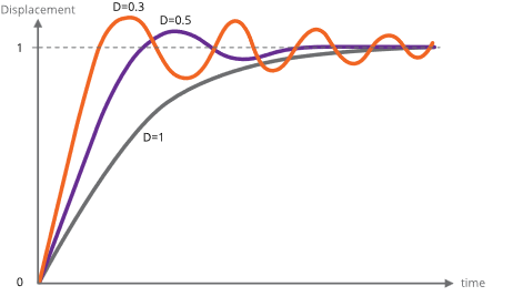
#### Control of resonance
The simplest method of controlling resonances is to avoid operation of the motor close to the resonant frequencies. It is usually possible to start a motor at rates in excess of 300 Hz if the load inertia is small, thereby completely avoiding the primary resonance. Resonances are not usually a problem when the motor speed is accelerating or retarding through the resonance frequency region.
If it is necessary to operate at slow speeds or with large load inertia, using microstepping helps. It effectively increases the stepping rate by the step division factor and reduces the amplitude of the step transients that excite the resonances. This is shown in the diagram below. Because both phases are energised in microstepping there are some other processes of interchange of energy between the windings which do not occur in the single step mode and these increase the damping factor.
In particularly difficult cases, modifying the step frequency at which transition from full stepping to microstepping occurs can be helpful.
A typical motor response to a single step and to a single step subdivided into eight microsteps is shown in the diagram below.
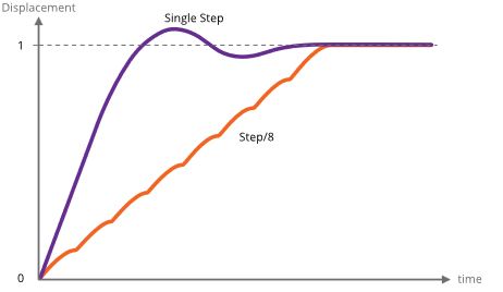
### Mechanisms for use with VCSMs
The following section is an introduction to this topic and is intended to indicate the major mechanical and vacuum considerations for various types of mechanisms. A working knowledge of mechanics and vacuum construction techniques is assumed. AML supply a range of standard mechanisms which can be customised, as well as designing custom mechanisms and components.
#### Rotation (Position control)
The load inertia coupled to the motor shaft should ideally be small compared to the rotor inertia of the motor. Load inertia up to two or three times that of the motor can be driven, without significant difference to the maximum start speed and acceleration which is achieved by the unloaded motor. Load inertia of around ten times that of the motor can be driven with absolute synchronism, provided care is taken over specifying the microstep and acceleration parameters. Larger inertia loads should be driven through reduction gearing.
Significant loads should have their centre of gravity on their axis of rotation, unless they are rotating in a horizontal plane.
Angular resolution at the motor shaft is limited to a single step of 1.8 °. The actual rest position within the step is determined mainly by the load friction and any torque imposed by the load on the motor at rest. If the rotor position is displaced θ° from the nominal step position, the restoring torque increases approximately in proportion to sin(100 × θ)° The maximum torque at the half step position is either the detent torque or the holding torque, depending on whether the motor is powered at rest. If the static friction and any torque due to an unbalanced load are known, this allows the rest position error to be estimated using the above approximation. The friction within the motor bearings is very low, so that a completely unloaded D42.2 motor will normally settle within 0.2 ° of the desired position if brought suddenly to rest from full stepping at 300 Hz.
Angular resolution may be improved by reduction gearing: this is discussed below.
#### Rotation (Speed control)
In some applications, the precise position of a rotating load is not important or can be deduced by other means, but the speed of rotation may need to be controlled very precisely. Beam choppers and sample rotators for control of deposition uniformity are applications of this type. An increased load inertia may be desirable to smooth out the stepping action of the motor. Loads of up to about 1000 times the inertia of the motor can be controlled by using long acceleration ramps. Some steps may be lost during acceleration and retardation of such loads, but precise synchronism at constant stepping frequency is easily achieved and recognised.
Significant rotating loads should be balanced, at least to the extent that the torque presented to the motor shaft is less than the detent torque of the motor. The motor torque requirement will then be dominated by that required to accelerate the load.
A typical example of a large inertia load was a 1.5 kg disk of uniform section, 20 cm in diameter. This was directly coupled to a D42.2 motor and rotated continuously in vacuum at 30 RPM.
#### Translation
Translation may be produced by a leadscrew and nut, wire-and-drum or rack-and-pinion mechanisms. The choice depends on the precision, length of travel, force and speed required. Leadscrew-based translators are capable of exerting forces of kilograms with resolutions of a few microns per step.
Accurate leadscrews are practical up to 400 mm long. With anti-backlash gearing between the motor and leadscrew resolution of one micron is practical. Anti-backlash nuts are not normally necessary for vertical motions. If a conventional nut is used with the leadscrew the load will be dominated by friction, especially if there is a reduction gear between the lead screw and the motor shaft which reduces the reflected load inertia.
Because of the lubrication restrictions and the slow speeds of UHV mechanisms the static friction is usually much more significant than dynamic friction. The optimum material for nuts is phosphor bronze and for lead screws is stainless steel with a diamond-like coating (DLC). DLC has a very low coefficient of friction in vacuum. Burnishing or sputtering a layer of pure Molybdenum Disulphide on the leadscrew may be useful in reducing friction and wear. The typical coefficient of friction between these materials is 0.1 and typical efficiencies are 40 % with ground trapezoidal threads. The gas load generated by frictional heating of the leadscrew is usually somewhat less than that of the motor.
The frictional losses in drum or rack drives are lower than in conventional leadscrew drives and considerations of inertia usually dominate. Rack and pinion drives are suitable for travel up to a few hundred millimetres and wire and drum mechanisms may be made several metres long. Another alternative for heavy loads is a studded stainless-steel band and matching pulleys. The repeatability and backlash of all these alternative translation drives are much worse than with screw-driven schemes.
#### Linear guides
Low-cost translation mechanisms can use simple bushes running on ground stainless-steel rods. A variety of carbon-reinforced polymer materials, such as PEEK, are suitable for the bushes.
'V' groove rollers and tracks and crossed-roller guides are suitable for more accurate translators. The former have the advantage of being practical to 1 metre and have minimal overall length for a given travel. Crossed-roller slides are more rigid and can support larger loads, but at higher cost. Both types have preload adjustments. 'V' rollers have smaller load-bearing surfaces and only have a rolling contact at a single point and are consequently liable to greater wear if heavily loaded. AML products of the VSM23 and VSM17 series are small-dimension examples of these types of mechanisms.
#### Reduction gearing
The inertia of loads coupled by reduction gearing is reduced at the motor in proportion to the square of the reduction ratio. Where reduction gearing is used for load matching, the spur gear meshing with the motor pinion will normally dominate the load inertia and it is important to keep its diameter small. Anti-backlash gears and standard pinions should be used in the gear train to damp any resonances in the mechanism. Gears for use in UHV should be designed for low friction without lubrication and with dissimilar materials in contact to avoid cold-welding. Nitrogen ion-implantation of the rolling surfaces or complete Titanium Nitride coating of gears are effective means of achieving this and other desirable properties in all-stainless-steel gear trains.
#### Bearings
Bearings for use in UHV should be unshielded and have a stainless steel cage and race. The balls should be either stainless steel coated with some other material or solid ceramic. As an alternative, all-stainless bearings having a PTFE composite component in the race (which is designed to transfer to the balls) are also suitable.
### Magnetic fields near motor
Motors should not be operated in fields of greater than 50 millitesla (500 gauss), as this will affect the performance while the field is present. Fields significantly greater than this may cause partial demagnetisation of the rotor, reducing the torque. Demagnetised motors can be restored by AML.
The leakage field of a motor is of the order of 1 millitesla (10 gauss) at 1 cm from the cylindrical surface of the motor in an axial direction and is present when the motor is not powered. Under drive an alternating component is added at the step frequency and its harmonics up to a few kHz. The field is easy to screen with Mu-metal or similar high permeability foil to below a few milligauss at the sides of the motor but is more difficult around the projection of the shaft. Early consideration of the interaction of stray fields on nearby equipment is recommended.
### Low power techniques
In the design of small mechanisms there are several factors that are not accurately known, or that have poor tolerances, for which generous allowances must be made. The result should be a conservative design where the available torque is in excess of the requirement. Some of this excess can be exchanged for increased running time or decreased outgassing in vacuum by various techniques. Used in combination the improvement can be very significant.
Most of the 'tuning' procedures below require the motor or mechanism to be run on the bench under realistic representative operating conditions while adjusting a parameter to the point where normal stepping operation fails. Erratic stepping is easy to see; a cable tie on the motor shaft makes a useful pointer. Familiarity with the SMD4 software and or remote interface is assumed.
#### Techniques applicable to all applications
The following techniques can be used in all applications to reduce motor power:
1. Run the motor at stepping rates between 500 Hz and 2 kHz, where its electromechanical efficiency is greatest, if possible
2. Reduce the acceleration for inertia-dominated loads
3. Reduce the phase current progressively to about 20% more than the minimum for consistent stepping. Some adjustment of the acceleration parameters may be needed
4. Make use of the run and acceleration current settings; try a higher current during acceleration to overcome inertia of a large load, and the minimum current possible during run to keep the load moving. This will reduce motor power dissipation versus using the same higher current all the time
5. Improve the heatsinking arrangements. A reduction in motor temperature decreases the winding resistance and increases its efficiency.
#### Techniques where step rates less than 100 Hz
For applications where operation below few hundred steps per second is satisfactory, use the following technique beyond those above. The desired effect is to complete each step as quickly as possible and remove or reduce the power to the minimum as soon as possible. Each step is completed in a few milliseconds, so that the power saving is progressively greater at lower speeds. Read and ensure that you understand the complete procedure before starting.
Set the target frequency VMAX equal to the start speed VSTART and steadily increase them both to determine the highest speed at which the motor will start. Take care when increasing the speed through the expected resonance range because the motor may not start in that range, although it may start reliably at higher speeds.
Configure PDDEL, IHD and IH to zero, to reduce motor current to zero as quickly as possible after each step is completed. Move the motor in single steps at the highest reliable starting speed, followed by a delay of a few milliseconds or more. This reduces power dissipation in the motor and so minimises temperature rise. It also has the consequence of reducing the damping factor at the time the power is reduced, so some experimentation with the parameters is required to ensure an adequate margin of stability is obtained.
### Possible causes of damage to VCSMs
Vacuum motors must be de-magnetised before disassembly and re-magnetised and cleaned after repair. For these reasons most will need to be returned to AML for repair. The notes below offer guidance on the avoidance of the most common problems and diagnostic advice.
#### Bearing damage
The ceramic balls in the bearings are very strong but more brittle than steel balls. Dropping the motor on its end will probably break some balls. The damage is occasionally visible and any roughness felt when rotating the shaft manually will indicate that this has happened.
#### Debris inside the motor
Foreign material can enter the motor via the pumping holes and gaps in the bearings. Particles of magnetic materials are particularly likely to be attracted through the pumping holes and they eventually migrate into the gap between the rotor and stator. They usually cause the rotor to stick at one or more points per revolution and can often only be felt when rotating in a specific direction. Fortunately, the larger motors have enough torque to grind them into a dust.
The main cause of this type of problem has been users modifying shafts. This can be avoided by sealing the motor inside a cleaned polyethylene bag and supervising the machining closely. Clean the projecting shaft and remove magnetic particles with a magnet before opening the bag. Remove the motor or similarly seal it if any filing or drilling of nearby components is done.
#### Overheating
Motors which have been heated to 230 °C will produce a much greater gas load thereafter, although their electromechanical performance may not be affected. In extreme cases, the insulating material will ablate and deposit itself as a yellow powder inside the motor case and on any cool surfaces in line with the pumping holes.
Motors can overheat very quickly in vacuum. This is very unlikely to happen with a properly connected SMD4 drive. Never use a drive capable of providing more than 1 amp of phase current and ensure that the drive current is removed as soon as the indicated temperature exceeds 190 °C. This is performed automatically by the SMD4.
# Maintenance and service
The SMD4 contains no user-serviceable parts.
### Cleaning
If the instrument requires cleaning, disconnect the power and all other connections, and wipe it down with a cloth slightly dampened with water or a mild detergent.
# Troubleshooting
| Problem
| Resolution
|
| Red and green status indicators off | Check that the power supply to SMD4 is correctly connected and meets the requirements given in section [Technical Information](https://bookstack.vps-da8d40f3.arunmicro.com/books/smd4-user-manual/page/technical-information) |
| Red status indicator flashing or lit solidly | Each indication corresponds to a fault, review section [Faults](https://bookstack.vps-da8d40f3.arunmicro.com/books/smd4-user-manual/page/operation#bkmrk-faults) |
| Motor does not move when commanded | Is a fault present? Check the red status indicator on the front panel, and use the SMD3 software or remote interface to determine the nature of the fault. After the fault has been fixed, run the CLR command, or use the reset fault input to restore normal operation
Check the motor wiring to the SMD3; disconnect the motor, and use a multimeter to measure the resistance of each phase, see section [Lead Identification](https://bookstack.vps-da8d40f3.arunmicro.com/books/smd4-user-manual/page/installation#bkmrk-lead-identification-1), which should be approximately 3 – 15 ohms
|
| Joystick does not work | Is joystick mode selected?
If you want to switch to joystick mode automatically on connection of the joystick, see setting [AUTOJS](https://bookstack.vps-da8d40f3.arunmicro.com/books/smd4-user-manual/page/communications-protocol#bkmrk-%C2%A0-15) and section [Joystick](https://bookstack.vps-da8d40f3.arunmicro.com/link/28#bkmrk-joystick). The joystick must be wired correctly for the auto-detect function to work as described in section [Joystick](https://bookstack.vps-da8d40f3.arunmicro.com/link/28#bkmrk-joystick).
|
# Storage and disposal
The product must be disposed of in accordance with the relevant local regulations for the environmentally safe disposal of systems and electronical components.
| 
| In the United Kingdom (UK) and European Union (EU), waste from electrical and electronic equipment (WEEE) is subject to legislation designed to prevent the disposal of such waste and to encourage proper treatment measures to minimize the amount of waste ultimately disposed to landfill. To view AML’s WEEE policy please visit: [https://arunmicro.com/documentation/WEEE\_procedure.pdf](https://arunmicro.com/documentation/WEEE_procedure.pdf)
|
# Assistance
In the first instance, contact the distributor or supplier of the equipment. Always quote the serial number of the instrument and firmware and software versions. Provide a written description of the problem. If the problem is related to a motor or mechanism manufactured by AML, include the serial number(s) of those items. Do not return products to AML without prior approval.
Arun Microelectronics Ltd
Tel: +44 (0)1903 884141
Email: info@arunmicro.com
Website: [arunmicro.com](https://arunmicro.com/)
# Compliance Certificate
| 
|  
|
This declaration of conformity is issued under the sole responsibility of the manufacturer.
| **Manufacturer:**
| Arun Microelectronics Limited
|
| **Address:**
| Unit 2, Bury Mill Farm, Bury Gate, Pulborough, RH20 1NN, United Kingdom
|
| **Object:**
| Stepper Motor Drive
|
| **Part No.:**
| SMD4
|
The object of the declaration described above is in conformity with the relevant UK Statutory Instruments (and their amendments), and the relevant European Union harmonisation legislation:
| **Statutory Instruments:**
| 2016 No. 1091
| The Electromagnetic Compatibility Regulations 2016
|
|
| 2016 No. 1101
| The Electrical Equipment (Safety) Regulations 2016
|
|
| 2012 No. 3032
| The Restriction of Use of Certain Hazardous Substances in Electrical and Electronic Equipment Regulations 2012
|
| **Directives:**
| 2014/30/EU
| EMC Directive
|
|
| 2014/35/EU
| Low Voltage Directive
|
|
| 2015/863
| RoHS Directive
|
| **Standards:**
| Harmonised and international/national standards and specifications:
|
|
| **EN 61010-1:2010+A1:2019**
| Safety requirements for electrical equipment for measurement, control and laboratory use
|
|
| **EN IEC 61800-3:2023**
| Adjustable speed electrical power drive systems
|
**Signature [](https://bookstack.vps-da8d40f3.arunmicro.com/uploads/images/gallery/2024-04/sig.PNG)**
*Mr. R Burling, Product Design Manager*
**Place, Date** Pulborough, April 2024