# Installation
### Before installation
**WARNING:** Read this manual carefully before installing and operating the SMD4. Observe the following safety instructions.
**WARNING:** All work described in this document may only be carried out by persons who have suitable technical training and the necessary experience or who have been instructed by the end-user of the product.
**WARNING:** Without proper training and necessary experience, damage to the equipment or personal injury might result.
**DANGER:** Danger of electric arcing! Never plug or unplug any connector while powered. Plugging or unplugging a motor while powered may damage or destroy the driver output stage.
### Unpacking
On receipt of the instrument remove all packing material and check that all items on the delivery note have been received. Report any damage or shortages to the company or distributor who supplied the instrument. The packing material has been specially designed to protect the instrument and should be retained for possible future use.
### Mechanical installation
The SMD4 is a freestanding instrument. It does not require mounting. Forced air ventilation is not required. The ambient operating temperature range is 10 °C to 60 °C.
### Front and rear panels overview
#### Rear panel
Most connections including power, communications and motor are on the rear panel. AML offer several air side cable options for making the connection between motor, encoder, and chamber feed throughs, see [motor wiring overview](https://bookstack.vps-da8d40f3.arunmicro.com/link/27#bkmrk-motor-wiring). Communications leads such as USB and network are readily available off the shelf.
[](https://bookstack.vps-da8d40f3.arunmicro.com/uploads/images/gallery/2025-06/smd4-rear-flat-render.JPG)
#### Front panel
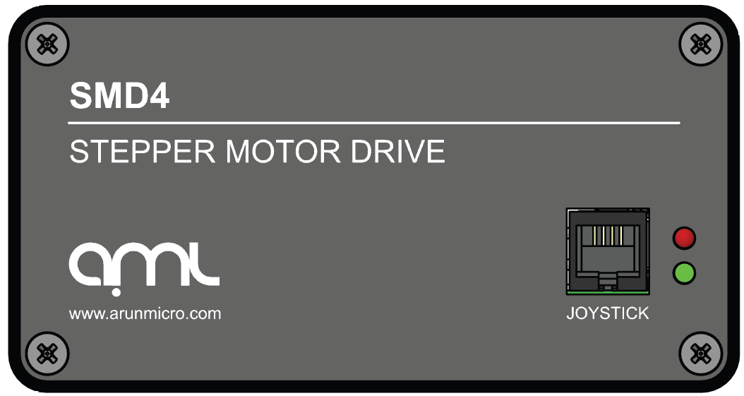
The front panel hosts status lights, see [troubleshooting](https://bookstack.vps-da8d40f3.arunmicro.com/link/32#bkmrk-page-title) and the joystick port.
[](https://bookstack.vps-da8d40f3.arunmicro.com/uploads/images/gallery/2024-02/dVMimage.png)
### Power
| Connector: Barrel power jack
2.1 mm pin, 5.6 mm hole
|
| [](https://bookstack.vps-da8d40f3.arunmicro.com/uploads/images/gallery/2024-03/Uv8dc.png)
| 48 Vdc input. Centre positive.
|
Power input for both internal logic circuits and the motor itself.
The power supply must:
- Meet the requirements set out in the [technical information](https://bookstack.vps-da8d40f3.arunmicro.com/books/smd4-user-manual/page/technical-information "Technical information") section of this document
- Provide reinforced or double insulation between mains and supply output
- Include protection against short circuit
A suitable power supply is included with the equipment.
**DANGER:** Danger of electric arcing! Never plug or unplug the power connector while powered.
### Communications
Configure and control the SMD4 using AML Device Control software, available as a free download from our website at [https://arunmicro.com/documents/software/](https://arunmicro.com/documents/software/)
Alternatively, use a terminal program, or your own application. APIs are available to help customers implement their own applications faster, see [here](https://bookstack.vps-da8d40f3.arunmicro.com/link/93#bkmrk-page-title) for details.
This section details the available interfaces.
#### USB
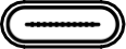
| Connector: USB-C
|
| [](https://bookstack.vps-da8d40f3.arunmicro.com/uploads/images/gallery/2024-03/x5.png)
| |
USB Type-C connection. The connection is reversible, and the plug may be inserted either way up.
The SMD4 appears as a virtual COM port when connected to the PC. No additional drivers are required.
#### LAN
| Connector: 8P8C RJ45
RJ45, 8 poles, 8 connections
|
| [](https://bookstack.vps-da8d40f3.arunmicro.com/uploads/images/gallery/2024-03/lan.png)
| |
10/100M network connection with Auto MDI-X.
#### RS232/485
| Connector: 8P8C RJ45
RJ45, 8 poles 8 connections
|
| [](https://bookstack.vps-da8d40f3.arunmicro.com/uploads/images/gallery/2024-03/rs232.png)
| 1 | |
| 2 | |
| 3 | |
| 4 | A+/Tx |
| 5 | B-/Rx |
| 6 | |
| 7 | |
| 8 | GND |
RS232 and RS485 share pins. Before connecting to them, use an alternate interface (USB or LAN) to configure the desired mode of operation. Undefined behaviour will result if the SMD4 is connected to an RS485 network when in RS232 mode or vice-versa.
There are two identical connectors, allowing SMD4 devices to be daisy-chained together.
An optional termination resistance can be enabled if required. This would typically be enabled on the last device on the bus, to reduce reflections and maintain signal integrity. The usage of this feature should be evaluated in the final system.
Configure the mode of operation (RS232 or RS485) before plugging a connector in. Do not make changes to the mode without first disconnecting both connectors. Undefined behaviour will result if the SMD4 is connected to an RS485 network when in RS232 mode or vice-versa.
##### Bussing
The dual connectors allow multiple SMD4s (or other devices) to be bussed together. There are several important considerations to be aware of when doing so:
- RS232 is not well suited to multi-drop; use RS485 for this purpose if at all possible. If using RS232, devices can receive and process commands, but will not respond and data cannot be returned to the host.
- Ensure all devices on the bus are in the the same mode (RS232 or RS485) and the same serial configuration (baud rate, etc.) matches between devices.
- When using text protocol, begin all commands with the '@' addressing prefix. This places the SMD4 into addressing mode which brings into force alternate communication rules that allow the SMD4 to function properly on a bus with other devices. This is discussed in the [Addressing](https://bookstack.vps-da8d40f3.arunmicro.com/link/51#bkmrk-addressing) section.
- Do not use text protocol commands without the addressing prefix. This will cause multiple devices to respond at once and the resulting bus contention may result in undefined behaviour.
### Motor
Read this section to learn about wiring up the motor, including air and vacuum side connections.
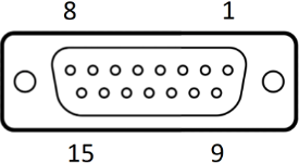
| Connector: DA15-F
D-Sub, 15 ways, female
|
| [](https://bookstack.vps-da8d40f3.arunmicro.com/uploads/images/gallery/2024-03/d-sub-15.png)
| 1 | Phase B2 |
| 2 | Phase B1 |
| 3 | Phase A2 |
| 4 | Phase A1 |
| 5 | Limit 1 |
| 6 | Limit 2 |
| 7 | Thermocouple negative |
| 8 | Thermocouple positive |
| 9 | GND
|
| 10 |
| 11 |
| 12 |
| 13 | RTD B2 |
| 14 | RTD B1 |
| 15 | RTD A |
**DANGER!** Danger of electric arcing! Never plug or unplug the connector while powered! Plugging or unplugging motor while powered may damage or destroy the driver output stages.
#### Limit switch inputs
There are two limits inputs; they can be configured to stop the motor when either is triggered. A limit input is triggered by shorting it to 'GND', usually with a mechanical switch mounted on the mechanism that the motor is driving. Logic level signals, for example, from optical or hall effect sensors may also be used.
Input polarity can be reversed to accommodate normally open or normally closed switches.
Limit 1 applies when the motor position counter is incrementing, and limit 2 applies when the motor position counter is decrementing.
Limits inputs include a pullup resistor. See section [Limits](https://bookstack.vps-da8d40f3.arunmicro.com/link/28#bkmrk-limits) for details.
**INFORMATION:** Limits inputs are duplicated on the I/O connector for maximum user flexibility in arranging wiring for the system. Limit signals on both this and the I/O connector are electrically connected. Do not apply different electrical potentials between like-named limits inputs otherwise a short will occur between the two.
#### Thermocouple
The thermocouple lead for motors equipped with the standard K-Type thermocouple should be connected here. If using a motor equipped with an RTD, this connection may be left open. Be sure to select the correct sensor type, see section [Temperature sensor selection](https://bookstack.vps-da8d40f3.arunmicro.com/books/smd4-user-manual/page/operation#bkmrk-temperature-sensor-s).
**INFORMATION:** To provide greater convenience in wiring to the vacuum chamber, the thermocouple input is included on the motor connector, rather than a dedicated micro K-Type thermocouple connector. This comes at the cost of reduced accuracy due to the parasitic thermocouple junctions that exist within the connector. This is accounted for by the looser accuracy specification for the thermocouple input over the RTD one, and a generous tolerance in the motor over temperature threshold as further insurance. Nonetheless, accuracy can be improved by avoiding large temperature gradients across the SMD4; for example, avoid placing the rear panel of the product in direct line of hot exhaust from other equipment.
#### RTD
For motors equipped with an RTD instead of a thermocouple, make the RTD connection here. If the RTD is not required, leave the connections open.
The RTD input is compensated for cable length by the three-wire connection.
#### Motor wiring overview
Connecting motors inside a vacuum chamber to the SMD4 comprises two tasks:
- Wiring the motor to a vacuum feedthrough installed in the chamber wall.
- Wiring the vacuum feedthrough to the SMD4.
AML supply vacuum feedthroughs, ready-made cabling, and components allowing custom cables to be easily manufactured. A typical setup is shown below and used for illustration throughout this section.
[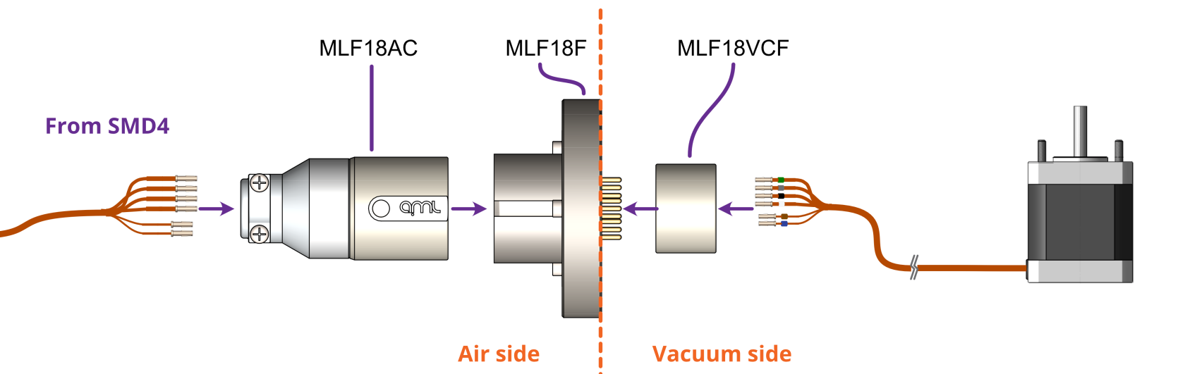](https://bookstack.vps-da8d40f3.arunmicro.com/uploads/images/gallery/2024-02/smd4-to-feedthrough-connection.png)
**INFORMATION:** Verify that the motor is working correctly before sealing the vacuum chamber. Rectifying mistakes afterwards is inconvenient.
#### Getting familiar with the motor leadouts
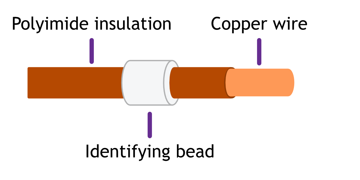
The motor leadout wires are polyimide film-wrapped, silver-plated OFHC solid copper and each is fitted with a 1.5 mm crimp socket terminal. The leads have a distinctive reddish/orange color. Each lead has a UHV compatible coloured glass bead fitted at the crimp end for identification. The phase leadout wires are much thicker than the thermocouple leadouts.[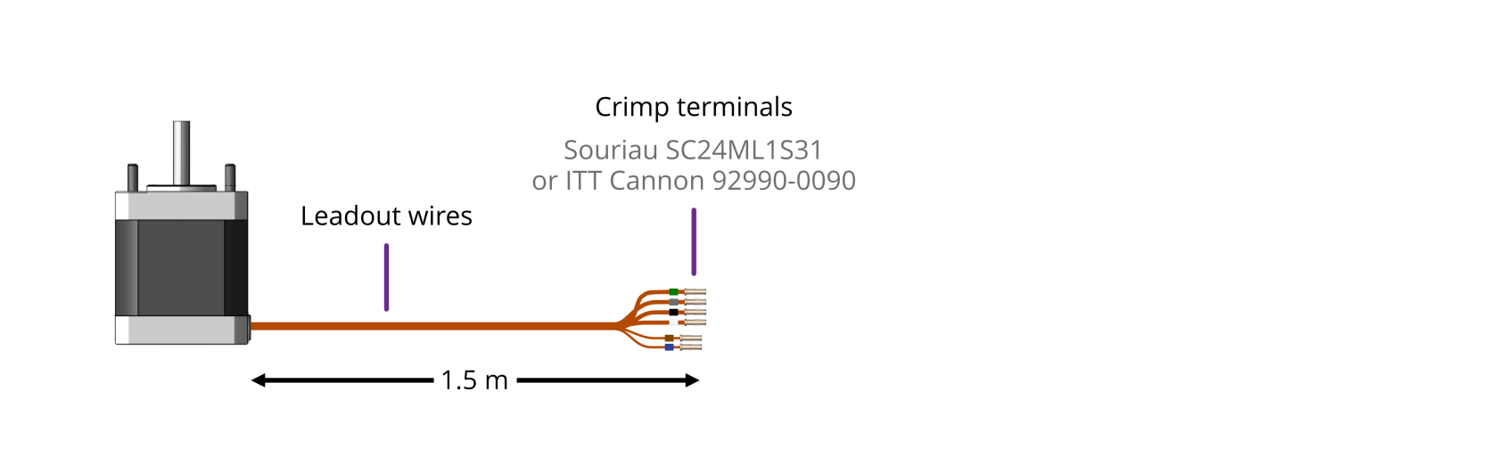](https://bookstack.vps-da8d40f3.arunmicro.com/uploads/images/gallery/2023-10/motor-leadout-wires-illustration-2.png)
| Motors equipped with a ***Thermocouple:*** | Motors equipped with an ***RTD:*** |
| [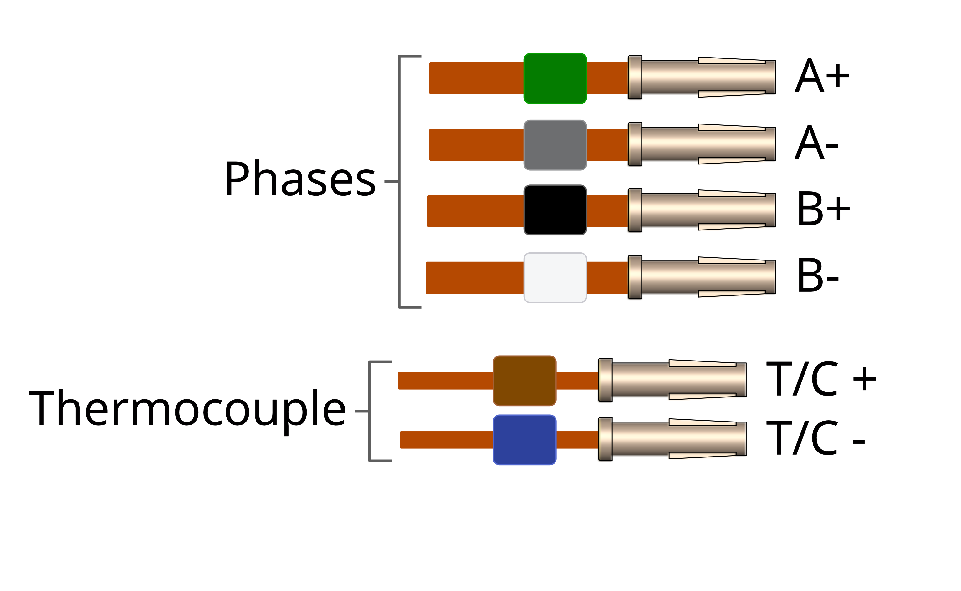](https://bookstack.vps-da8d40f3.arunmicro.com/uploads/images/gallery/2023-10/motor-leadout-wires-rtd-illustration.png) | [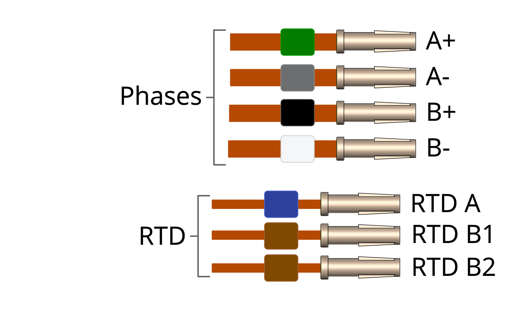](https://bookstack.vps-da8d40f3.arunmicro.com/uploads/images/gallery/2023-10/motor-leadout-wires-rtd-illustration.png) |
When working with the motor leads:
- Keep the leadout wires of each phase twisted together (A+ and A- twisted together, B+ and B- twisted together)
- Keep the thermocouple or RTD leads twisted together
#### Identifying the leadouts when coloured beads are missing
If the identification beads are missing, the wires can be identified using an inexpensive multimeter, and a magnet. The multimeter must be capable of measuring resistance with a resolution of about 1 ohm.
**Phase leadouts**
These are the four thicker leadouts. Identify the two motor phases by their resistance, which will be in the range of 3 to 15 ohms, depending on the motor type. There is no electrical connection between the two phases, to the thermocouple/RTD or the case of the motor. Most of the resistance is in the windings of the motor and is virtually unaffected by shortening of the leads. Connect each phase to the appropriate drive terminals. The resistance of the wires from the feedthrough to the drive must be less than a few ohms.
| **Thermocouple Leadouts**
The thermocouple wires are much thinner than the phase leads, and there are two of them. If three wires are present, the motor has an RTD installed, see below for details. The thermocouple is insulated from the rest of the motor.
The two leads are of different material; one is made from Alumel, which is weakly magnetic, and the other Chromel, which is not. Use a magnet to find the Alumel wire, then connect as shown below.
| | Lead | Connected to terminal marked | | Alumel | Alumel, N, - (minus) or coloured blue |
| | Chromel | Chromel, P, + (plus) or coloured brown | |
|
| **RTD Leadouts**
As per the thermocouple leads, but three instead of two leads. These must be identified by resistance; one pair of wires are connected at the motor end. These will measure a few ohms depending on cable length and are the ‘B1’ and ‘B2’ connections, which are interchangeable.
The remaining wire is the ‘A’ connection and should measure around 100 ohms to either ‘B1’ or ‘B2’.
| | Lead | Connected to terminal marked | | A | A, or coloured blue |
| | B1 | Chromel,B1, or coloured brown | | | B2 | B2, or coloured brown | |
|
#### Reversing motor direction
If the motor direction is opposite to that required, simply swap the wires of one phase to reverse direction of rotation. For example, swap the A+ and A- leads and the motor will spin the other way.
#### Wiring the motor to a vacuum feedthrough
AML motors are commonly connected via an MLF18 feedthrough or a standard D-Sub feedthrough, but any suitable feedthrough may be used. This section discusses these options.
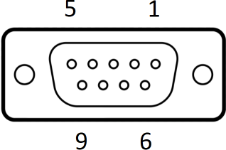
##### **9-Way D-Sub**
The VC9D-40CF 9-way D-Sub male feedthrough is suitable for one motor fitted with either a thermocouple or 3-wire RTD. The standard crimp terminals supplied with AML motor leadout wires should be removed and replaced with a VC9DF PEEK D-Sub female connector and crimp terminals. An optional VC9DB cable strain relief is also available.
[](https://bookstack.vps-da8d40f3.arunmicro.com/uploads/images/gallery/2024-03/dsub9-expanded.PNG)
**Motor wires pinout for the VC9DF**
The illustration below shows the view into the non-mating side of the connector, into which the motor leads should be inserted, as shown below. Pass the wires through the backshell before crimping.
| Connection | Colour | Pin | Pin Insertion Side |
| Phase A1 | Green | 4 | [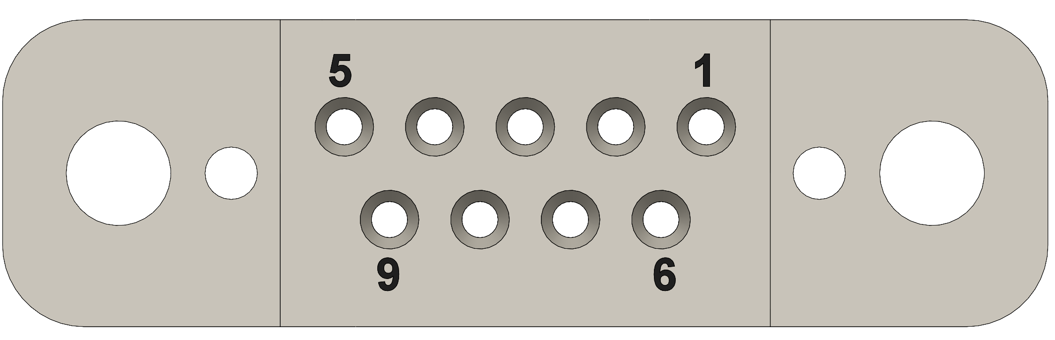](https://bookstack.vps-da8d40f3.arunmicro.com/uploads/images/gallery/2024-03/d-sub9-female.PNG) |
| Phase A2 | Grey | 3 |
| Phase B1 | Black | 2 |
| Phase B2 | White | 1 |
| Thermocouple + | Brown | 8 |
| Thermocouple - | Blue | 7 |
| RTD A | Blue | 5 |
| RTD B1 | Brown | 6 |
| RTD B2 | Brown | 9 |
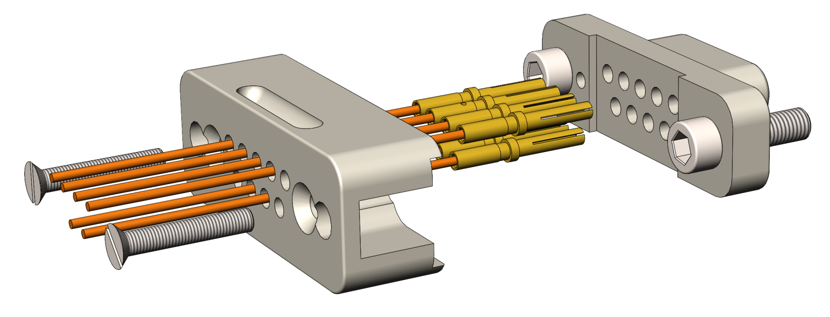
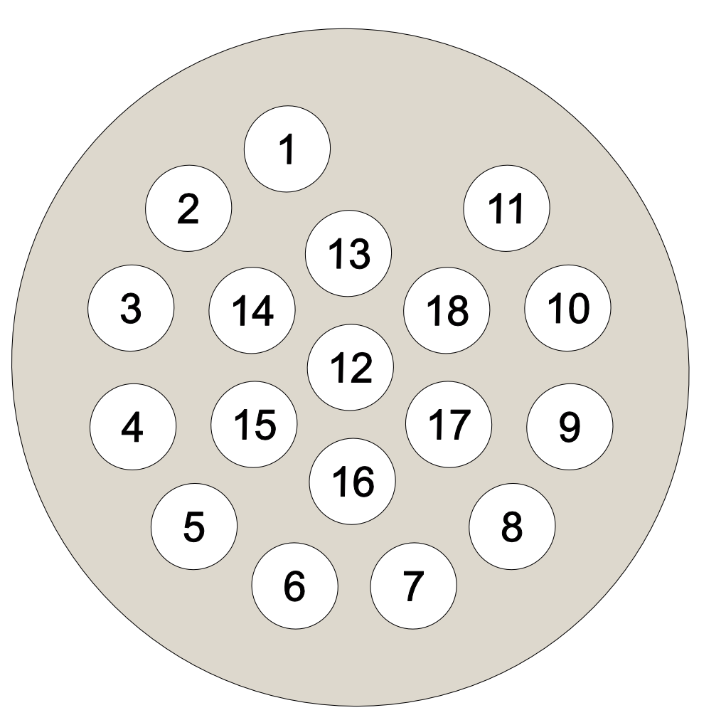
##### **18-Way MLF18**
The MLF18F feedthrough has 18 x 1.5 mm gold-plated feedthrough pins and is suitable for up to three motors fitted with thermocouples or up to two motors fitted with 3-wire RTDs. An internal bakeable connector, MLF18VCF, is available into which the crimp terminals on the motor leads are inserted. This significantly reduces the risk of short-circuits and makes the installation more convenient.
| Using the MLF18F feedthrough and MLF18VCF vacuum side connector: | Alternatively, plug crimps directly onto the feedthrough pins of the MLF18F: |
| [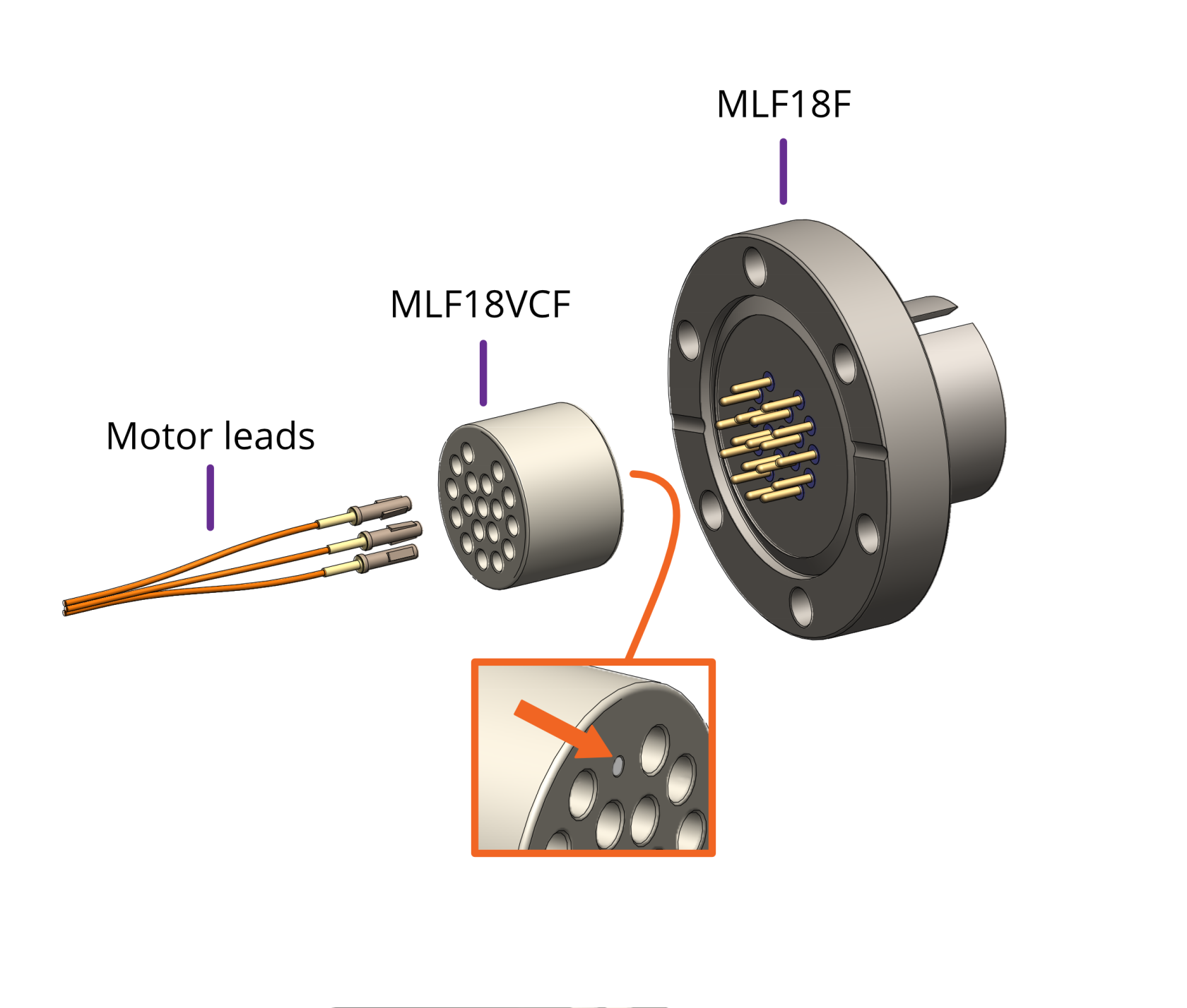](https://bookstack.vps-da8d40f3.arunmicro.com/uploads/images/gallery/2023-10/vacuum-side-motor-connection-mlf18vcf.png)
| [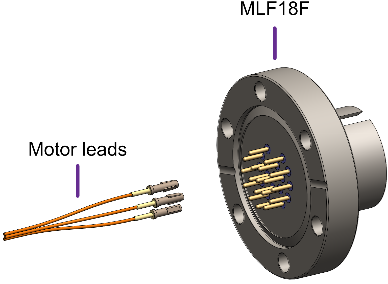](https://bookstack.vps-da8d40f3.arunmicro.com/uploads/images/gallery/2023-10/vacuum-side-motor-connection-straight-into-mlf18f-3.png)
|
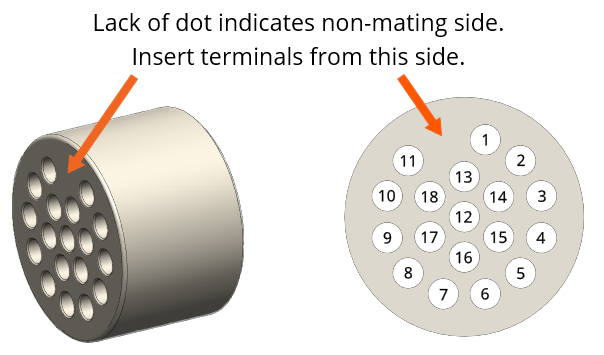
| Mating side identified by dot. Motor lead terminals should be inserted in the other side. |
|
| **Standard pinout for the MLF18VCF** |
| The illustration below shows the view into the non-mating side of the connector, into which the motor leads should be inserted, as shown below. |
| Connection | Colour | Motor 1 | Motor 2 | | Phase A1 | Green | 1 | 7 | | Phase A2 | Grey | 3 | 9 | | Phase B1 | Black | 2 | 8 | | Phase B2 | White | 4 | 10 | | Thermocouple + | Brown | 5 | 11 | | Thermocouple - | Blue | 6 | 12 | | RTD A | Blue | 13 | 16 | | RTD B1 | Brown | 14 | 17 | | RTD B2 | Brown | 15 | 18 |
| [](https://bookstack.vps-da8d40f3.arunmicro.com/uploads/images/gallery/2023-10/mlf18ac-pinning.png) |
##### **Using other feedthroughs**
AML stepper motors can be ordered with either a K-Type thermocouple, or 3-wire PT100 RTD. The former requires 6 pins, and the latter 7 pins.
When using motors installed with a thermocouple, it is not necessary to use a thermocouple vacuum feedthrough or extension wires, as the error introduced by incompatible feedthrough material is usually less than 5 °C and the temperature measurement is not required to be very precise.
| **Preparation of motor leadouts for connection to other feedthroughs** |
| If making custom terminations for the motor leads, the installed crimps must be removed, and the wire ends stripped of insulation. Standard motors are fitted with Polyimide film-wrapped leads (illustrated below), and radiation-hard motors are fitted with polyimide-enamelled leads.
Polyimide is strong, flexible and abrasion-resistant and therefore difficult to strip. The simplest method of stripping polyimide film is to cut a ring with a sharp knife and withdraw the cylinder of insulation over the end of the wire.
Be careful not to mark the conductor surface with the knife. Strip the enamelled radiation-hard leads by scraping with a sharp knife. Either type of lead may be stripped with a suitable high-speed rotary stripper. Do not use a thermal stripper.
| [](https://bookstack.vps-da8d40f3.arunmicro.com/uploads/images/gallery/2023-10/polyamide-wire-stripping.png) |
| **Rated voltage** | >= 300 V rms |
| **Rated current** | > 1.5 A rms |
| **Construction** | Twisted pairs plus overall screen.
Foil screen plus drain wire (of same or greater cross-sectional area as main cores) acceptable.
Foil plus braided screen better.
|
| **Resistance** | Maximum cable length is limited by the resistance of the cores; total round-trip cable resistance per phase should be kept to less than a few ohms.
Consult the cable manufacturer's data for these details. Excessive cable length causes a reduction in phase voltage at the motor compromising speed/torque characteristics.
The RTD circuit is compensated for cable length.
|
| **Qty. cores** | As required.
One motor requires 6 cores when fitted with a thermocouple, or 7 if fitted with an RTD
|
**Signal pairing:** Cable cores must be twisted together in pairs. This reduces radiated emissions from the cable and improves the immunity of the RTD and thermocouple signals to interference; use:
- One pair for phase A
- One pair for phase B
- One pair for thermocouple
- One pair for RTD signals A and B1, plus spare wire from another pair for B2.
Do not pair phase wires with temperature sensor wires.
**Wiring up to the MLF18AC airside connector**
The MLF18AC is supplied with comprehensive instructions detailing correct usage of the connector. The pinout to match with the standard MLF18F + MLF18VCF pinning described in section [Motor wiring](https://bookstack.vps-da8d40f3.arunmicro.com/books/smd4-user-manual/page/installation#bkmrk-motor-wiring) is shown below. Note that the illustration shows the MLF18AC looking into the non-mating side of the connector, i.e. the side into which crimps are inserted.
| Connection | Colour | Motor 1 | Motor 2 | | Phase A1 | Green | 1 | 7 | | Phase A2 | Grey | 3 | 9 | | Phase B1 | Black | 2 | 8 | | Phase B2 | White | 4 | 10 | | Thermocouple + | Brown | 5 | 11 | | Thermocouple - | Blue | 6 | 12 | | RTD A | Blue | 13 | 16 | | RTD B1 | Brown | 14 | 17 | | RTD B2 | Brown | 15 | 18 |
| Looking into the non-mating face of the MLF18AC, into which crimps are inserted
|
| [](https://bookstack.vps-da8d40f3.arunmicro.com/uploads/images/gallery/2023-10/mlf18ac-pinning.png) |
### Encoder
| Connector: DA-26-F
D-Sub, 26 ways, female, high density.
|
| [](https://bookstack.vps-da8d40f3.arunmicro.com/uploads/images/gallery/2024-11/d-sub-26.png)
| 1 | 5V |
| 2 | BiSS MA- |
| 3 | BiSS MA+ |
| 4 | GND |
| 5 | BiSS SLO- |
| 6 | Reserved, do not make connection to this pin. |
| 7 | GND |
| 8 | 5V |
| 9 | GND |
| 10 | INC E |
| 11 | INC A- |
| 12 | INC A+ |
| 13 | INC B- |
| 14 | INC B+ |
| 15 | INC Z- |
| 16 | INC Z+ |
| 17 | INC P |
| 18 | INC Q |
| 19 | Reserved, do not make connection to this pin.
|
| 20 |
| 21 |
| 22 |
| 23 |
| 24 | BiSS SLO+ |
| 25 | 5V |
| 26 | GND |
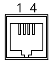
### I/O
| Connector: DE9-F
D-Sub, 9 ways, female
|
| [](https://bookstack.vps-da8d40f3.arunmicro.com/uploads/images/gallery/2024-03/d-sub-9.png)
| 1 | GND |
| 2 | Fault (Output, open collector) |
| 3 | Limit 1/positive |
| 4 | Enable |
| 5 | Step |
| 6 | Reset fault (Input, active low) |
| 7 | Limit 2/negative |
| 8 | SDE COM |
| 9 | Direction |
#### Fault output and fault reset
The SMD4 disables the motor under certain fault conditions, see section [Faults](https://bookstack.vps-da8d40f3.arunmicro.com/books/smd4-user-manual/page/operation#bkmrk-faults). When this happens, the open collector ‘Fault’ output is set and may be used to signal to an external controller that the SMD4 is in a fault state.
Fault states are latching; once set the fault condition must be removed and the fault reset before normal operation may resume using either a remote interface command (see [CLR](https://bookstack.vps-da8d40f3.arunmicro.com/books/smd4-user-manual/page/communications-protocol#bkmrk-sys%3Aclr-%E2%80%93-clear-faul)) or pulling the ‘Reset fault’ signal to ‘GND’. This does not apply to the ‘EN’ (enable) input when in step direction mode, i.e. the enable input is not latching, and normal operation will resume immediately on restoring the enable input state. See section [Faults](https://bookstack.vps-da8d40f3.arunmicro.com/books/smd4-user-manual/page/operation#bkmrk-faults) for details.
#### Limits
Duplicated from the [motor connector](#bkmrk-limits).
#### Step, direction and enable
The step direction enable interface is an industry-standard interface allowing an external motion controller to generate stepping sequences, bypassing the SMD4’s internal motion controller. The inputs are galvanically isolated with three opto-isolators, and share a common connection, ‘SDE COM’. See section [Step/Direction](https://bookstack.vps-da8d40f3.arunmicro.com/books/smd4-user-manual/page/communications-protocol#bkmrk-step%2Fdirection) for details.
### Joystick
| [](https://bookstack.vps-da8d40f3.arunmicro.com/uploads/images/gallery/2023-10/lzGdtdpower-connector-pinout.png)
| 1 | GND |
| 2 | CW |
| 3 | CCW |
| 4 | DETECT |
For connection of a two-button joystick allowing basic motor control, for example, during commissioning. AML supply the SMD3 Joystick, part number ‘SMD3JOY’, which is compatible with the SMD4, for this purpose. The joystick can be used any time the SMD4 is in remote mode. See [here](https://bookstack.vps-da8d40f3.arunmicro.com/link/28#bkmrk-using-the-joystick) for more on joystick functionality.
If designing your own joystick or device to connect to this port:
- Inputs have internal pull-ups
- Activate the function by shorting ‘CW’, ‘CCW’ or ‘DETECT’ to pin 1, ‘GND’
- ‘DETECT’ is used to signal to the SMD4 that the joystick is plugged in, and thus should be left shorted to GND.
Logic level signals may also be used; 12 V max.
### Indicator lights
| **Green** | Status/power indicator
Blinks when the operation mode changes and while in bake.
|
| **Red** | Error indicator
On or flashing indicates and error. See section [Faults](https://bookstack.vps-da8d40f3.arunmicro.com/books/smd4-user-manual/page/operation#bkmrk-faults) for fault indications. When a fault is present, motor operation is disabled.
|