Axial and Radial Loads
1. Axial and Radial Loads on AML Stepper Motor Bearings
AML stepper motors are fitted with two bearings, which support the rotor at each end of the housing. They are extremely reliable in clean vacuum situations and have useful service lives of decades with low imposed loading. The two principal causes of failure are both due to misuse: break-up of the ball cage due to ingress of contaminants or damage due to extreme shock loads such as are caused by dropping the motor on its shaft end. Axial and radial loads imposed on the motor should be avoided where possible by the design of the mechanism to which the motor is applied. Loads comparable to the bearing ratings will shorten their lives in unpredictable ways. It will usually be more convenient to replace bearings in a mechanism than in a motor, which has to be de-magnetised, cleaned, remagnetised and baked during any service.
1.1. Axial Loads
The bearing at the opposite end to the principal mounting face of the motor is preloaded against the motor end cap by a spring. The free travel of the spring is about 0.3 mm and is fully exercised by a force of 2.5 kg against the shaft end. It is important to design linear mechanisms so that this free travel is not added to the backlash in the mechanism. This can be achieved by preload springs, gravity or by decoupling the motor from the load by gearing. Linear mechanisms with leadscrews can exert considerable axial forces if they are stalled against rigid end stops. All standard AML mechanisms are designed with vernier stops, which stall the motor directly, avoiding this potential problem. If there is any possibility of a linear mechanism crashing into rigid obstructions, it may be necessary to use torque-limiting to reduce the resulting force. If a linear mechanism stalls due to excessive friction, no additional axial load is imposed on the leadscrew.
Refer to the motor datasheet on the AML website for axial load limits.
1.2. Radial Loads
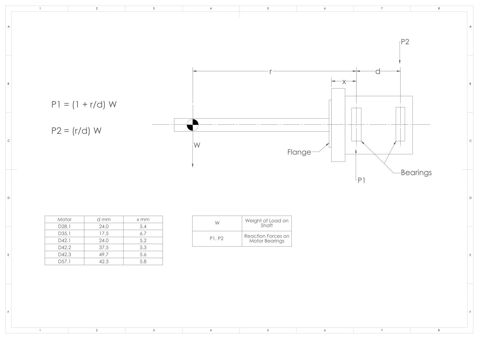
Radial loads on motors arise in two main ways. The first is a simple cantilever extension on the shaft, where the forces on the bearings can be easily calculated by reference to the diagram which is appended. Note that the radial forces on the bearings are magnified by the extension acting as a lever. The second arises in linear mechanisms where the leadscrew or other extension is directly coupled to the motor shaft and supported or constrained by a nut or bearing. Any misalignments will give rise to significant radial forces on the motor bearings. Use the maximum radial load on our datasheet as a reference to assess the radial loads in your system. To calculate the maximum reaction forces for each motor at P1 and P2 you can use the equations on the diagram. Once you have these limits you can assess if the radial loads in your system are acceptable.
The diagram should be used as a guide based on confirmed maximum load limits on AML datasheet.

