Feedthrough Requirements
Motor wiring
Overview
Connecting motors inside a vacuum chamber to the SMD4 comprises two tasks:
-
Wiring the motor to a vacuum feedthrough installed in the chamber wall.
-
Wiring the vacuum feedthrough to the SMD4.
AML supply vacuum feedthroughs, ready-made cabling, and components allowing custom cables to be easily manufactured. A typical setup is shown below and used for illustration throughout this section.
INFORMATION: Verify that the motor is working correctly before sealing the vacuum chamber. Rectifying mistakes afterwards is inconvenient.
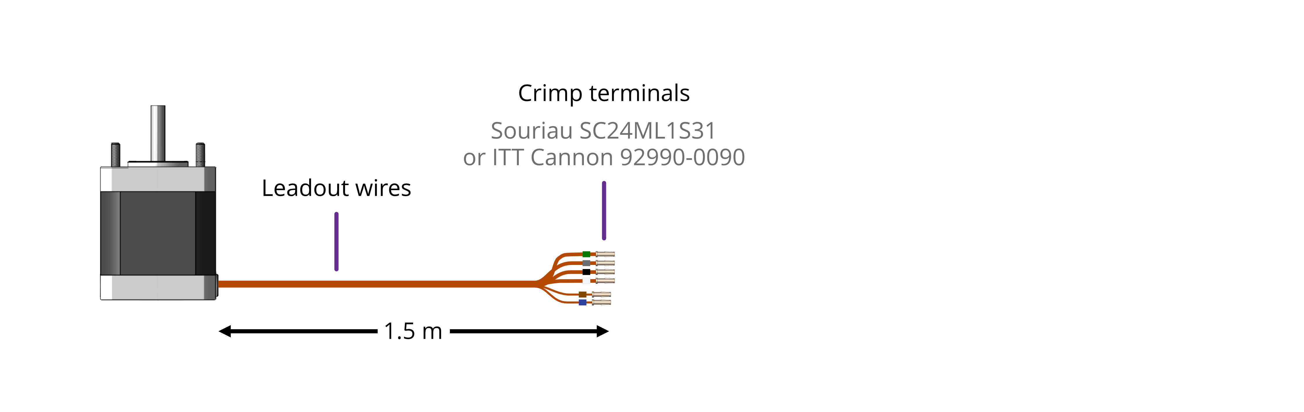
Lead identification
The motor leadout wires are self-coloured polyimide film-wrapped, silver-plated OFHC solid copper and each is fitted with a 1.5 mm crimp socket terminal. They are supplied fitted with UHV compatible coloured glass beads for identification. The phase leadout wires are much thicker than the thermocouple leadouts. The leadout wires of each phase should be twisted together.
| Motors equiped with a Thermocouple: | Motors equiped with an RTD: |
 |
|
If the identification beads have been removed, the wires can be identified using an inexpensive multimeter, and a magnet. The multimeter must be capable of measuring resistance with a resolution of about 1 ohm.
|
Thermocouple Leadouts The thermocouple wires are much thinner than the phase leads, and there are two of them. If three wires are present, the motor has an RTD installed, see below for details. The thermocouple is insulated from the rest of the motor. |
|
|||||||||
|
RTD Leadouts As per the thermocouple leads, but three instead of two leads. These must be identified by resistance; one pair of wires are connected at the motor end. These will measure a few ohms depending on cable length and are the ‘B1’ and ‘B2’ connections, which are interchangeable. The remaining wire is the ‘A’ connection and should measure around 100 ohms to either ‘B1’ or ‘B2’. |
|
||||||||||||
Phase leadouts
These are the four thicker leadouts. Identify the two motor phases by their resistance, which will be in the range of 3 to 15 ohms, depending on the motor type. There is no electrical connection between the two phases, to the thermocouple/RTD or the case of the motor. Most of the resistance is in the windings of the motor and is virtually unaffected by shortening of the leads. Connect each phase to the appropriate drive terminals. The resistance of the wires from the feedthrough to the drive must be less than a few ohms.
Note regarding reversal of rotation
Upon completion of wiring, there is a 50 % probability that the direction of rotation will be reversed from the desired or conventional sense. To rectify this, exchange the connections to one of the phases. For example, locate the Phase A + and Phase A – connections, and swap them around. This can be done on air or vacuum side while the chamber is still open.
Wiring motor to a vacuum feedthrough
AML motors are commonly connected via an MLF18 feedthrough or a standard D-Sub feedthrough.
9-Way D-Sub
The VC9D-40CF 9-way D-Sub male feedthrough is suitable for one motor fitted with either a thermocouple or 3-wire RTD. The standard crimp terminals supplied with AML motor leadout wires should be removed and replaced with a VC9DF PEEK D-Sub female connector and crimp terminals. An optional VC9DB cable strain relief is also available.
Motor wires pinout for the VC9DF
The illustration below shows the view into the non-mating side of the connector, into which the motor leads should be inserted, as shown below. Pass the wires through the backshell before crimping.
| Connection | Colour | Pin | Pin Insertion Side |
| Phase A1 | Green | 4 | 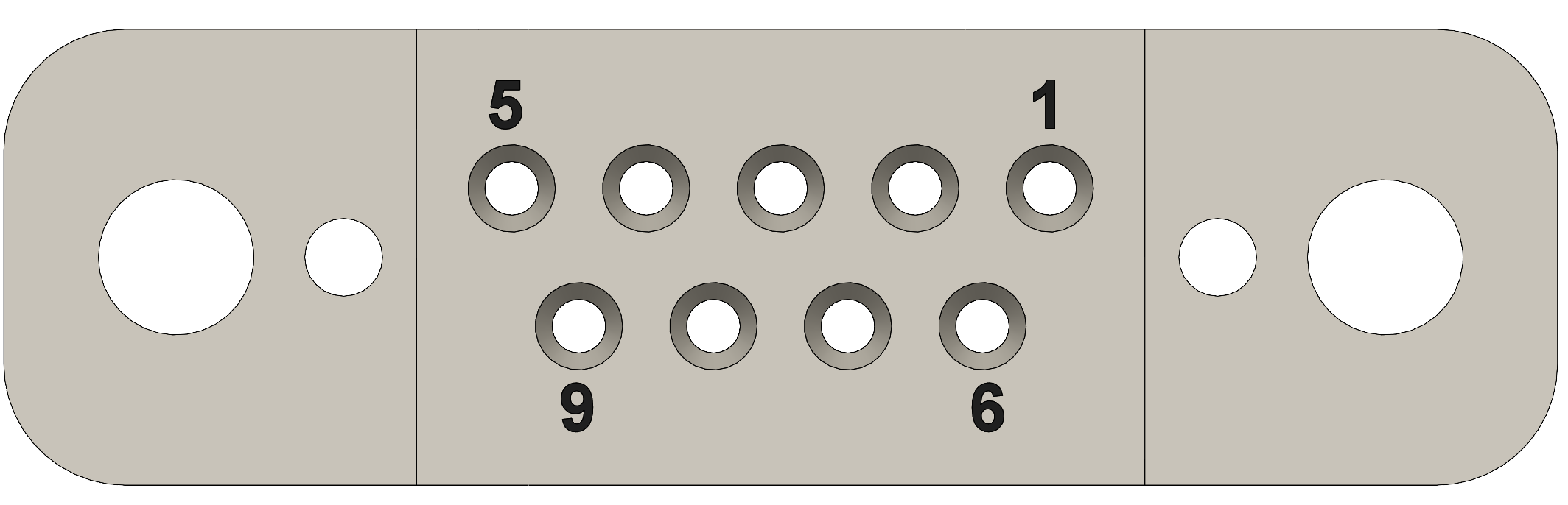 |
| Phase A2 | Grey | 3 | |
| Phase B1 | Black | 2 | |
| Phase B2 | White | 1 | |
| Thermocouple + | Brown | 8 | |
| Thermocouple - | Blue | 7 | |
| RTD A | Blue | 5 | |
| RTD B1 | Brown | 6 | |
| RTD B2 | Brown | 9 |
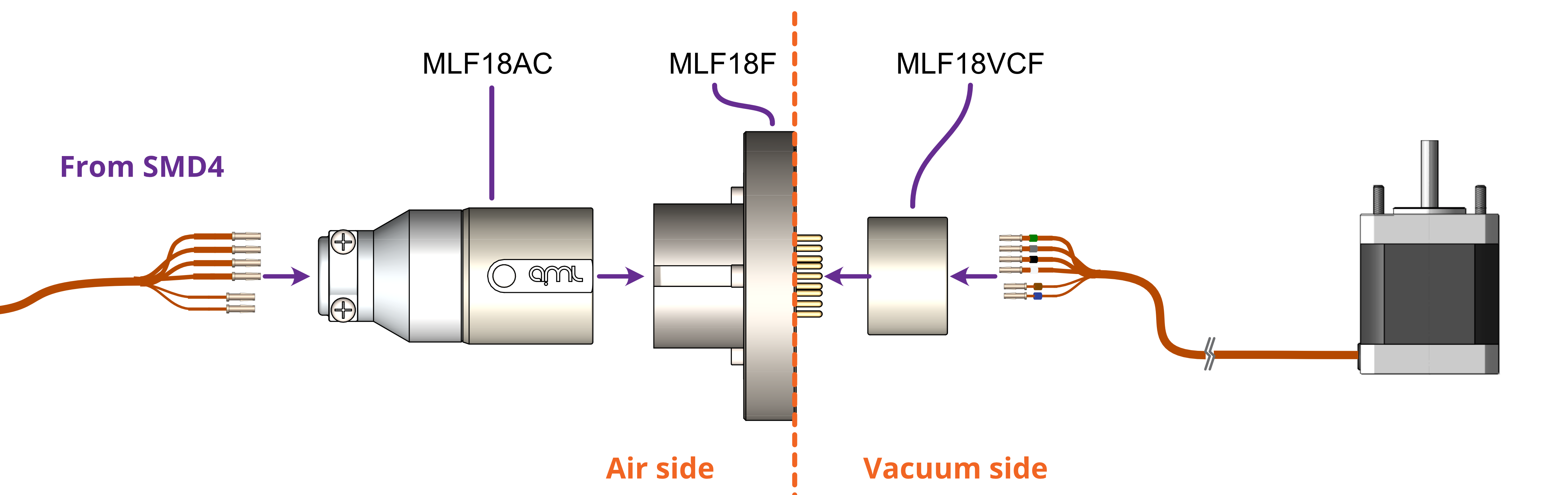
18-Way MLF18
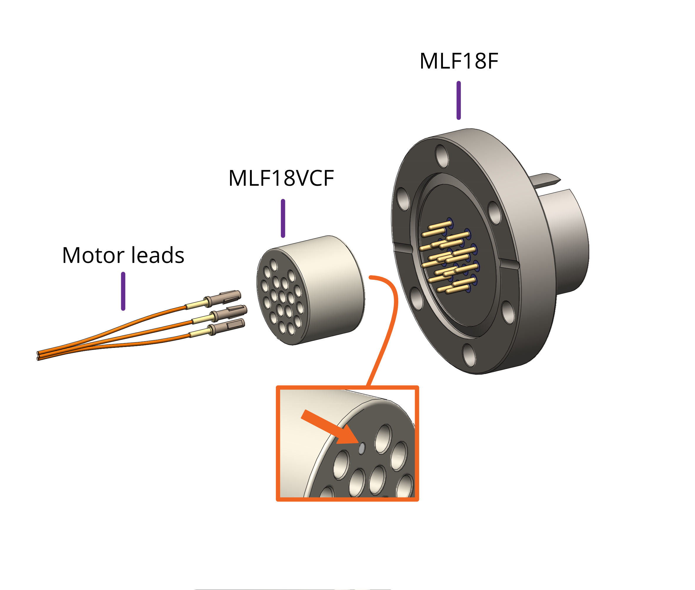
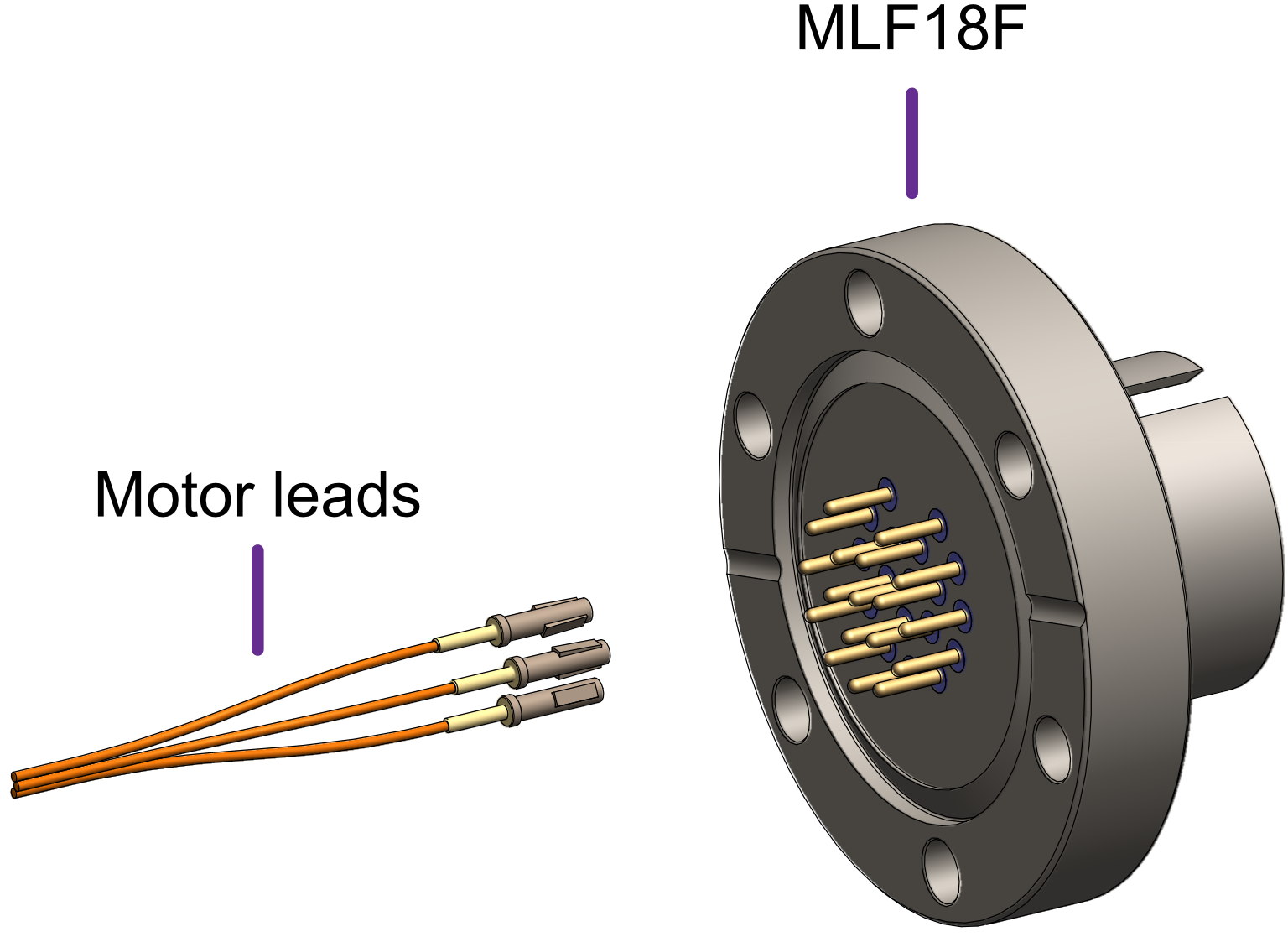
The MLF18F feedthrough has 18 x 1.5 mm gold-plated feedthrough pins and is suitable for up to three motors fitted with thermocouples or up to two motors fitted with 3-wire RTDs. An internal bakeable connector, MLF18VCF, is available into which the crimp terminals on the motor leads are inserted. This significantly reduces the risk of short-circuits and makes the installation more convenient.
| Using the MLF18F feedthrough and MLF18VCF vacuum side connector: | Alternatively, plug crimps directly onto the feedthrough pins of the MLF18F: |
|
|
|
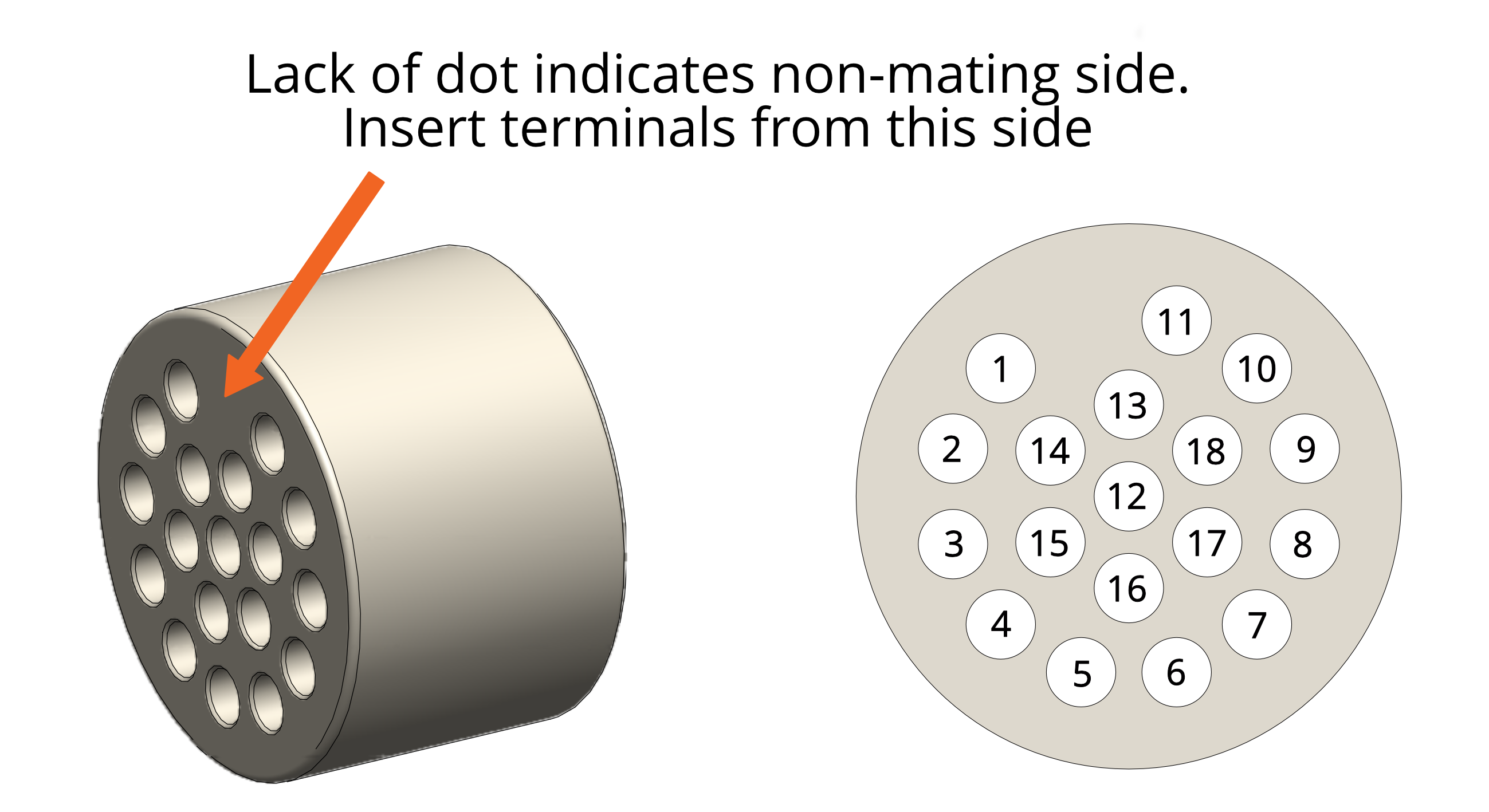
| Mating side identified by dot. Motor lead terminals should be inserted in the other side. |
| Standard pinout for the MLF18VCF | |||||||||||||||||||||||||||||||||||||||||
| The illustration below shows the view into the non-mating side of the connector, into which the motor leads should be inserted, as shown below. | |||||||||||||||||||||||||||||||||||||||||
|
 |
||||||||||||||||||||||||||||||||||||||||
Using other feedthroughs
AML stepper motors can be ordered with either a K-Type thermocouple, or 3-wire PT100 RTD. The former requires 6 pins, and the latter 7 pins.
When using motors installed with a thermocouple, it is not necessary to use a thermocouple vacuum feedthrough or extension wires, as the error introduced by incompatible feedthrough material is usually less than 5 °C and the temperature measurement is not required to be very precise.
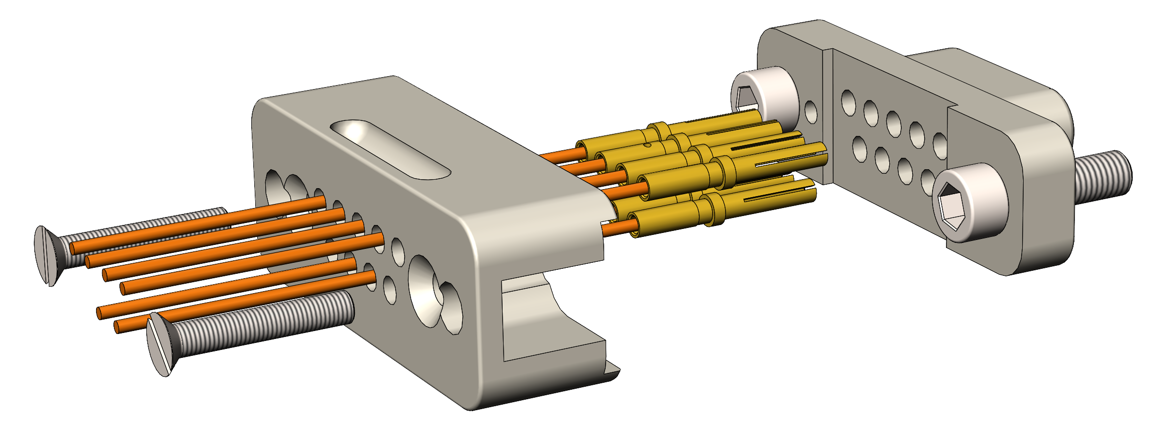
| Preparation of motor leadouts for connection to other feedthroughs | |
|
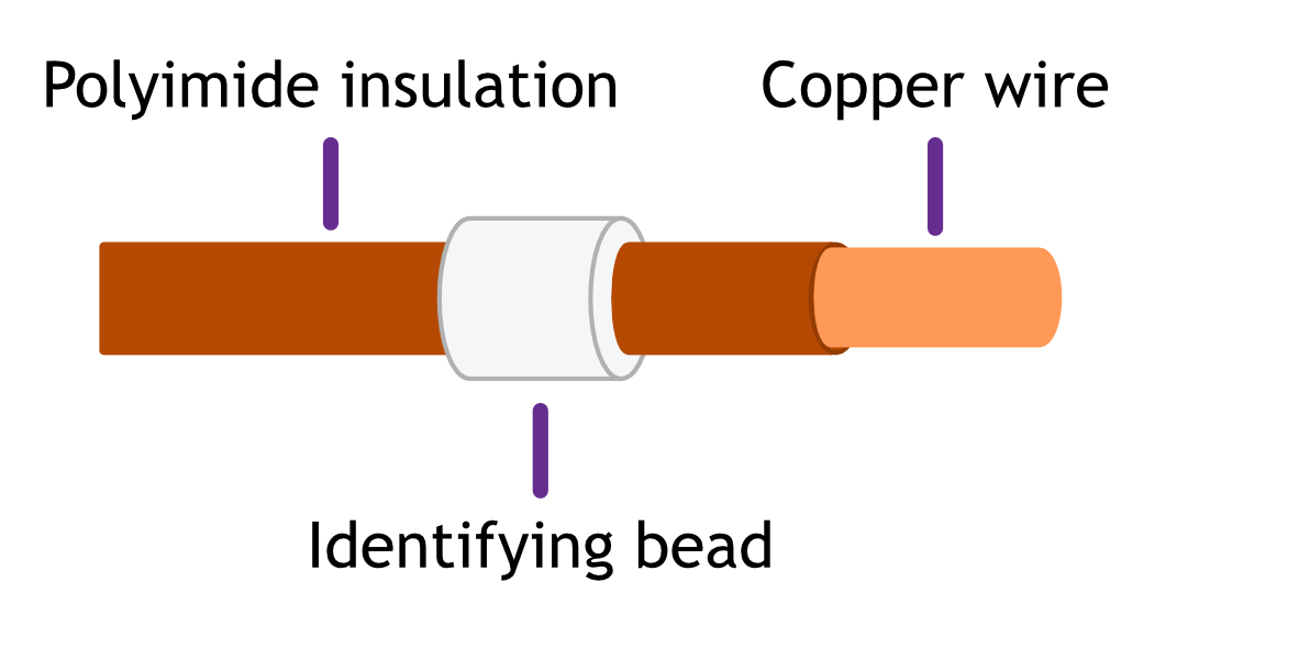
If making custom terminations for the motor leads, the installed crimps must be removed, and the wire ends stripped of insulation. Standard motors are fitted with Polyimide film-wrapped leads (illustrated below), and radiation-hard motors are fitted with polyimide-enamelled leads.
Polyimide is strong, flexible and abrasion-resistant and therefore difficult to strip. The simplest method of stripping polyimide film is to cut a ring with a sharp knife and withdraw the cylinder of insulation over the end of the wire. Be careful not to mark the conductor surface with the knife. Strip the enamelled radiation-hard leads by scraping with a sharp knife. Either type of lead may be stripped with a suitable high-speed rotary stripper. Do not use a thermal stripper. |
 |