Identifying and Connecting the Leads
The lead-out wires are self-coloured polyimide film-wrapped, silver-plated OFHC copper and each is fitted with a 1.5 mm crimp socket terminal. They are supplied fitted with UHV compatible coloured glass beads for identification. Lead-out wires are supplied 1.5 metres long but can be shortened if required. For replacement crimp terminals use Souriau SC24ML1S31
(AML part no. MLF18SKT) or equivalent.
If the identification beads have been removed, then use the following procedure. An ohmmeter with resolution down to about 1 ohm is required to identify the two phase windings: most inexpensive multimeters are suitable.
The phase lead-out wires are much thicker than the temperature sensor wires. Radiation-hard motors may have multi-strand leads. Identify the two motor phases by their resistance, which will be in the range of 3 to 15 ohms, depending on the motor type. There is no electrical connection between the two phases or to the temperature sensor or the case of the motor.
Most of the resistance is in the windings of the motor and is virtually unaffected by shortening of the leads. Connect each phase to the appropriate drive terminals. The resistance of the wires from the feedthrough to the drive must be less than a few ohms.
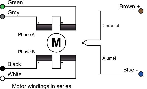
The thermocouple wires are much thinner than the phase leads. The thermocouple is insulated from the rest of the motor. The Alumel wire may be identified with a magnet since it is weakly magnetic. At the controller the Alumel lead should be connected to the terminal marked Alumel, N, -, or coloured blue, and the Chromel lead should be connected to the terminal marked Chromel, P, + or coloured brown. The temperature measurement is not required to be very precise, so it is not necessary to use thermocouple-compatible feedthroughs or extension wires. If compatible materials are used then they must be connected the correct way round.
Standard Wiring: |
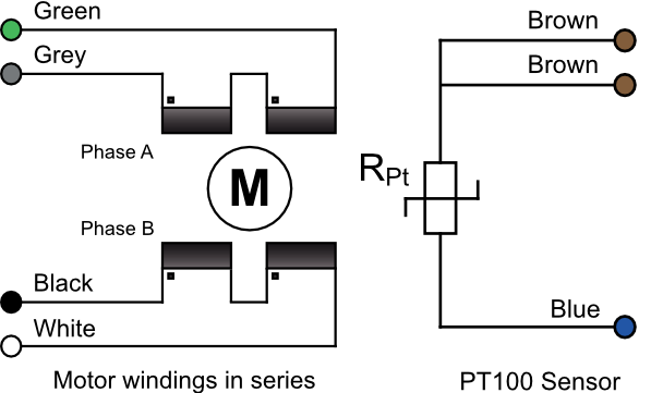
Option P Wiring: |
  |
  |