Installation
Before installation
WARNING: Read this manual carefully before installing and operating the SMD3. Observe the following safety instructions.
Qualified personnel
WARNING: All work described in this document may only be carried out by persons who have suitable technical training and the necessary experience or who have been instructed by the end-user of the product.
WARNING: Without proper training and necessary experience, damage to the equipment or personal injury might result.
Additional safety and warning notices
DANGER: Danger of electric arcing! Never plug or unplug any connector while powered. Plugging or unplugging a motor while powered may damage or destroy the driver output stages.
Unpacking
On receipt of the instrument remove all packing material and check that all items on the delivery note have been received. Report any damage or shortages to the company or distributor who supplied the instrument. The packing material has been specially designed to protect the instrument and should be retained for possible future use.
Mechanical installation
The SMD3 may be mounted via the front panel and or underside flanges, in any orientation. Forced air ventilation is not required. The ambient operating temperature range is 10 °C to 60 °C.
Connecting
Rear panel
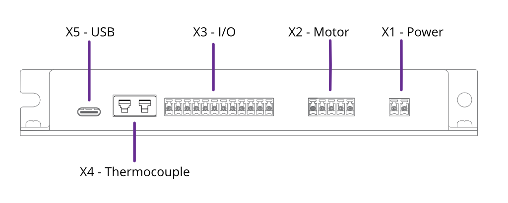
The Power, Motor and I/O sockets use 3.5 mm pitch pluggable rewireable terminal blocks. These are suitable for 28 – 16 AWG (1.5 mm2 max.) stranded wire. Strip insulation to approx. 6 – 7 mm before securing the wire in the terminal block.
Connectors are supplied for X1, X2, X3 and X4. Replacement connectors are available from IMO Precision Controls, part number 20.1550M/X-E where ‘X’ is the number of ways. For example, the part number for the power connector pluggable terminal block would be 20.1550M/2-E. These are readily available from electronics distributors.
X1 - Power
![]()
Power input for both internal logic circuits and the motor itself.
The power supply must meet the following requirements:
- 15 – 67 V DC regulated supply, 30 W minimum
- Reinforced or double insulation between mains and supply output
DANGER: Danger of electric arcing! Never plug or unplug the connector while powered.
CAUTION: In the event of reverse polarity, a short circuit will occur between GND and V+ through an internal power diode. Therefore, an external fuse must be installed in the supply line.
The fuse should be sized:
- Greater than the current consumption of the SMD3 when operating the connected motor
- Less than the maximum current output of the power supply
- Considering the voltage of the supply
INFORMATION: Choice of input voltage affects motor performance; operating at the maximum voltage possible (67 Vdc) will maximise motor torque at higher speeds.
X2 - Motor

|
1 |
GND |
|
2 |
Phase A1 |
|
3 |
Phase A2 |
|
4 |
Phase B1 |
|
5 |
Phase B2 |
Motor output. Connection of the motor to the vacuum feedthrough, and vacuum feedthrough to the SMD3 is discussed in section Motor Wiring.
Custom motor cables must be built to the following specification to ensure continued compliance with EMC standards and correct function:
-
Four cores, comprising two twisted pairs plus screen. A foil screen plus drain wire is acceptable; a foil plus braid screen is better
-
The screen must be connected via as short a wire as possible to pin 1, ‘GND’, using insulated wire
-
Rated voltage >= 300 V rms
-
Rated current > 1.5 A rms
Maximum cable length is limited by the resistance of the cores; total round trip cable resistance per phase should be kept to less than few ohms. Consult the cable manufacturers data for these details.
DANGER! Danger of electric arcing! Never plug or unplug the connector while powered! Plugging or unplugging motor while powered may damage or destroy the driver output stages.
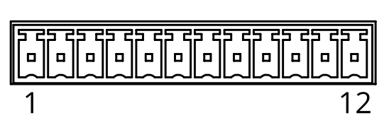
X3 - I/O
X4 - Thermocouple
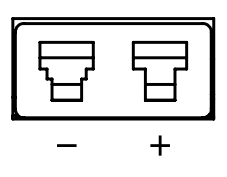
The thermocouple lead for motors equipped with the standard K-Type thermocouple should be connected here. If using a motor equipped with an RTD, this connection may be left open. Be sure to select the correct sensor type, see section Temperature sensor selection.
The connection is for use with a standard IEC Miniature K-Type thermocouple plug. These are colour coded green for K-Type thermocouples.
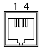
X5 - USB
Front panel
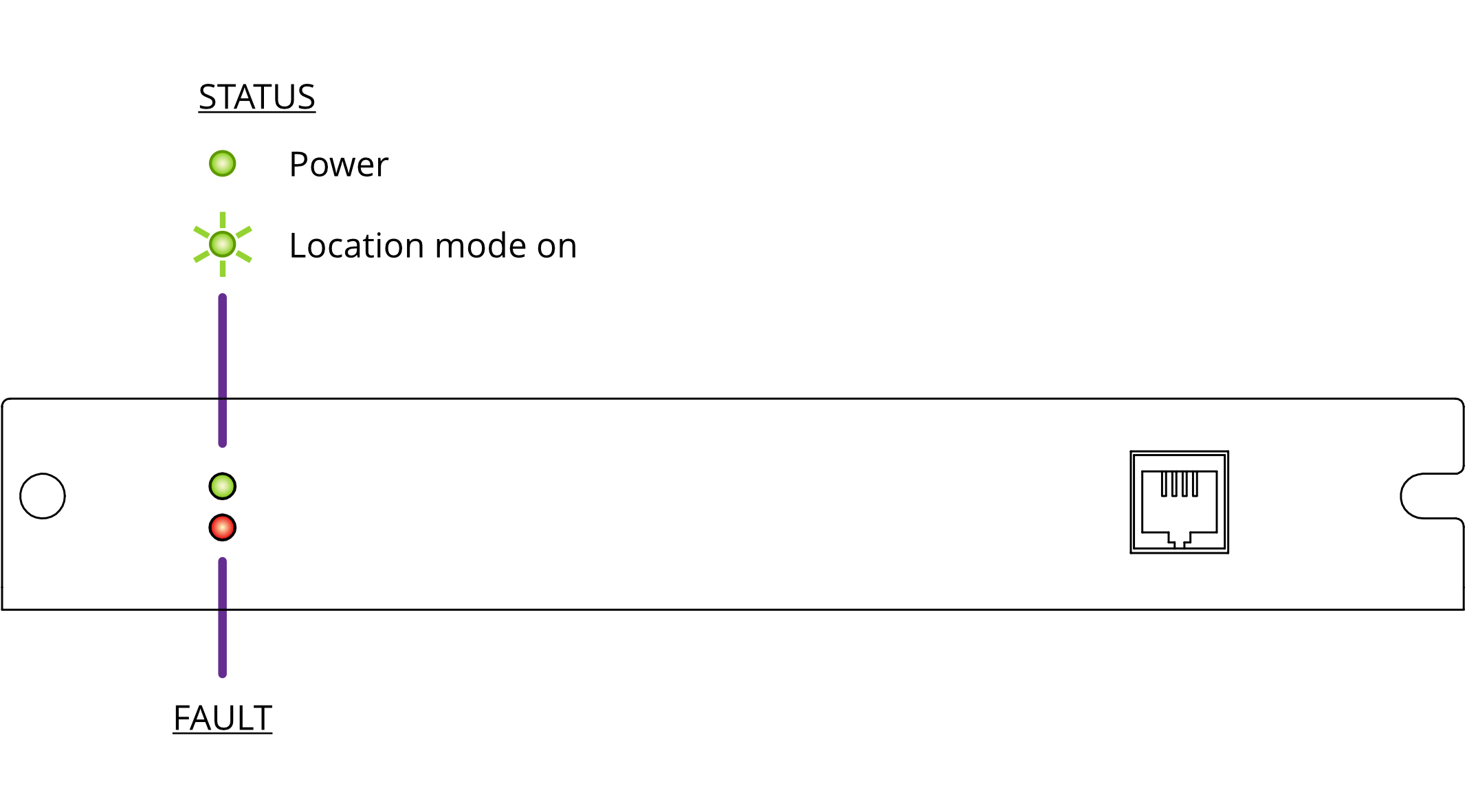
The fault indicator flashes or remains lit if the SMD3 is in a fault state (see section Faults for fault indications). When a fault is present, motor operation is disabled.
X6 - Joystick
For connection of a two-button joystick allowing basic motor control, for example, during commissioning. AML supply the SMD3 Joystick, part number ‘SMD3JOY’ for this purpose. On connection, the SMD3 automatically switches to joystick mode.
- If designing your own joystick or device to connect to this port:
- Inputs have internal pull-ups.
- Activate the function by shorting ‘CW’, ‘CCW’ or ‘DETECT’ to pin 1, ‘GND’.
- Pin 4, ‘DETECT’ is used to signal to the SMD3 that the joystick is connected and trigger automatic switch to joystick mode. If not required, leave the pin unconnected. This requires joystick mode to be manually selected.
Logic level signals may also be used; 12 V max.