Software
Installation and setup
The SMD3 is compatible with the AML Device Control software, which can be downloaded from the Software page on our website: https://arunmicro.com/documents/software/
- Connect all SMD3 devices to your computer, using a USB lead, and power them on.
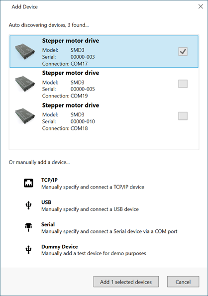
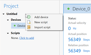
- Start the AML Device Control software and click ‘Add device’ in the top left corner
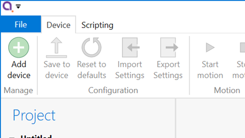
USB connected SMD3 devices should automatically appear in the list. Select all devices that you wish to add and click “Add n selected devices”
Overview
The default layout of the software is shown below.
Project panel
A status indicator next to each device shows the current status of each device according to these colours:
|
Colour |
Description |
|
|
Device connected and ready |
|
|
Bake mode running, limit switch triggered or joystick connected |
|
|
Device in a fault state |
|
|
Device disconnected |
Device properties panel
Select one or more devices in the project panel; their properties are displayed and can be edited here. A blank is shown for properties which are different across the selected devices. As each property is selected, help text appears at the bottom of the panel describing the configuration option in more detail.
-
Some properties allow selection of one of several choices, for example, temperature sensor selection:

-
Others such as ‘Run current’ simply require a numeric value to be entered
-
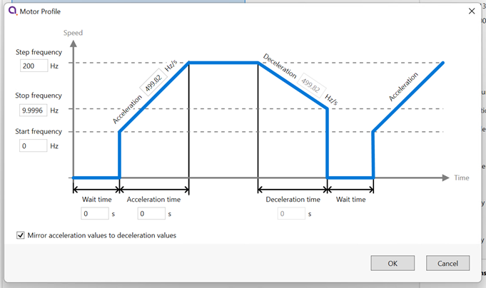
Others allow values to be entered directly, or the three dots button to the right to be clicked. This opens a window, allowing a more complex value to be input, for example, ‘Acceleration’ allows input in the native units or seconds:
System work area
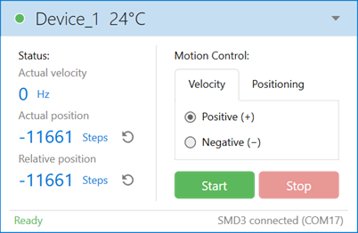
Controller windows for each device appear in this area. Windows can be arranged as desired and will automatically ‘snap’ to a grid making it easy to keep them neatly organised.
Controller window
INFORMATION: Be aware that the synchronisation between multiple SMD3s is not specified or guaranteed when controlling them in this way; delays within the computer, software, and USB connection to the SMD3 mean that each SMD3 will start or stop its motion at a slightly different moment, therefore this option is not suitable for performing complex co-ordinated movements across multiple axes.
Ribbon
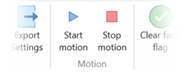
Contains buttons for all actions. Within the software, buttons can be hovered over for more information.

Saving projects
- The SMD3 itself, with the use of the ”Save to device” command. If the “Save to device” command is not used, settings will revert to their previous values on power cycling.
- In the software project file.
If the serial number of a connected SMD3 matches that of one in the project file that is open: The configuration given in the project file prevails, and the SMD3 configuration is synchronised to match that in the project file. Note that unless you use the save changes to hardware function, the original configuration of the SMD3 is not overwritten, and will be restored on power cycle or by using the load command to restore the configuration from flash.
If the serial number of a connected SMD3 does not match any of those in the project file that is open: The SMD3 is considered a new device in the project, and the project file will be initialised from the configuration found in the SMD3 itself. After this point, the first behaviour outlined above applies.
INFORMATION: In the first case above, configuration items that require the SMD3 to be in standby will not be correctly synchronized if the SMD3 is not in standby when the software connects.
Scripting
A brief description of each function/command is presented below the scripting section. Here is an overview of the scripting area:
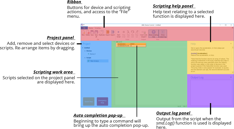
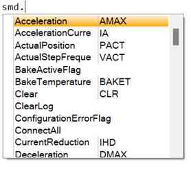
The auto completion popup can be shown using the ‘Ctrl-K’ keyboard shortcut.
Information on the available SMD3 device specific commands can be found in section USB Interface of this manual. Serial command mnemonics will be auto completed by the script editor. The arguments of each scripting function are identical to those shown in section Command Reference, however, the format of querying and commanding is different. The example below shows how the SMD3 mode can be set and queried:
|
smd.Mode(2); smd.Mode(); |
// Set the SMD3 mode to 2 (remote) // Query state of mode |
The ribbon contains scripting specific buttons.

Function specific to the SMD3 software
|
Function |
Description |
|
Add |
bool Add(string serial) Add a new device to the project. Returns true if the device has been detected and added to the project. serial: Device serial number. |
|
ClearLog |
void ClearLog( ) Clear command line. |
|
ConnectAll |
void ConnectAll( ) Connect all devices in the project. |
|
Delayms |
void Delayms(int value) Delay in milliseconds. value: Minimum: 0 Maximum: 2^31 -1 |
|
DelaySeconds |
void DelaySeconds(int value) Delay in seconds. value: Minimum: 0 Maximum: 2147483 |
|
DisconnectAll |
void DisconnectAll( ) Disconnect all devices in the project. |
|
Log |
void Log(string value) Print value to the command line. |
|
Name |
bool Name(string serial, string name) Change name of the device. Returns true if the device has been found and name changed. serial: Device serial number. name: Device new name. |
|
Remove |
bool Remove(string serial) Remove a device from the project. Returns true if the device has been detected and removed from the project. serial: Device serial number. |
|
RemoveAll |
void RemoveAll( ) Remove all devices from the project. |
|
Select |
bool Select(string[ ] devices) Returns true if all the requested devices have been selected. devices: Name of the device(s). |
|
SelectAll |
void SelectAll( ) Select all devices. |
|
SelectNone |
void SelectNone( ) Deselect all devices. |
Functions that query the SMD3 and that are not also available as a serial command are listed below. Note that these all return an array rather than a single value, with each array element corresponding to the data from one SMD3.SMD3. The order of the array elements corresponds to the order in which the SMD3 devices are selected. For example, suppose the “X-axis”, “Y-axis” and “Z-axis” named devices were selected with the command “smd.Select(“Z-axis”, ”X-axis”, ”Y-axis)”, to check the standby flag of the “X-axis” device, use MotorStandbyFlag()[1].
|
Function |
Description |
|
BakeActiveFlag |
bool[] BakeActiveFlag() Returns true if the bake mode is running. |
|
ConfigurationErrorFlag |
bool[] ConfigurationErrorFlag() Returns true if the motor configuration is corrupt. |
|
EmergencyStopFlag |
bool[] EmergencyStopFlag() Returns true if the motor is disabled by software. |
|
ExternalEnableFlag |
bool[] ExternalEnableFlag() Returns true if the external enable input is high. |
|
ExternalInhibitFlag |
bool[] ExternalInhibitFlag() Returns true if the external enable input is disabling the motor. |
|
IdentModeActiveFlag |
bool[] IdentModeActiveFlag() Returns true if the ident mode is active. |
|
JoystickConnectedFlag |
bool[] JoystickConnectedFlag() Returns true if the joystick is connected. |
|
LimitNegativeFlag |
bool[] LimitNegativeFlag() Returns true if the negative limit is active. |
|
LimitPositiveFlag |
bool[] LimitPositiveFlag() Returns true if the positive limit is active. |
|
MotorOverTemperatureFlag |
bool[] MotorOverTemperatureFlag() Returns true if the motor temperature is greater than 190 °C. |
|
MotorShortFlag |
bool[] MotorShortFlag() Returns true if a motor phase to phase or phase to ground short has been detected. |
|
MotorStandbyFlag |
bool[] MotorStandbyFlag() Returns true if the motor is stationary. |
|
TargetVelocityReachedFlag |
bool[] TargetVelocityReachedFlag() Returns true if the motor is at the target step frequency. |
|
TemperatureSensorOpenFlag |
bool[] TemperatureSensorOpenFlag() Returns true if the selected temperature sensor is open circuit. |
|
TemperatureSensorShortedFlag |
bool[] TemperatureSensorShortedFlag() Returns true if the selected temperature sensor is shorted (not applicable to thermocouple) |

