Installation
Before installation
WARNING: Read this manual carefully before installing and operating the SMD4. Observe the following safety instructions.
Qualified personnel
WARNING: All work described in this document may only be carried out by persons who have suitable technical training and the necessary experience or who have been instructed by the end-user of the product.
WARNING: Without proper training and necessary experience, damage to the equipment or personal injury might result.
DANGER: Danger of electric arcing! Never plug or unplug any connector while powered. Plugging or unplugging a motor while powered may damage or destroy the driver output stage.
Additional safety and warning notices.
Unpacking
On receipt of the instrument remove all packing material and check that all items on the delivery note have been received. Report any damage or shortages to the company or distributor who supplied the instrument. The packing material has been specially designed to protect the instrument and should be retained for possible future use.
Mechanical installation
The SMD4 is freestanding instrument. It does not require mounting. Forced air ventilation is not required. The ambient operating temperature range is 10 °C to 60 °C.
Connecting
Rear panel

Power
Connector: Barrel power jack
2.1 mm pin, 5.6 mm hole
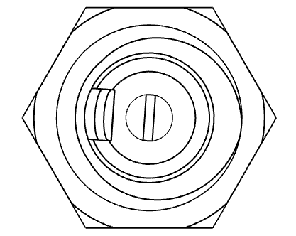
48 V, pin is positive
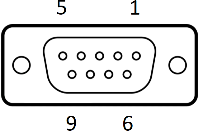
I/O
Connector: DE9-F
D-Sub, 9 ways, female
Motor
Connector: DA15-F
D-Sub, 15 ways, female
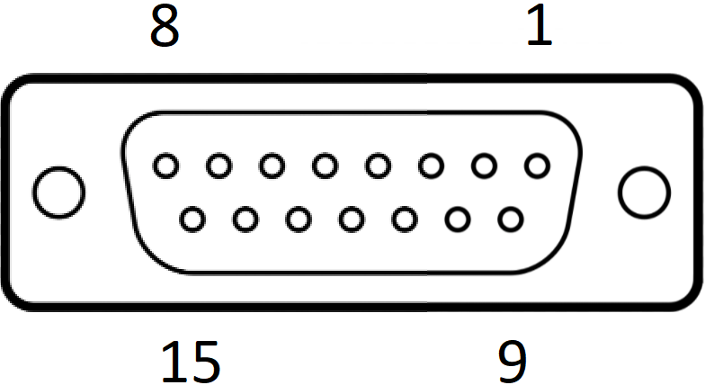
1 Motor B2 2 Motor B1 3 Motor A2 4 Motor A1 5 Limit 1 6 Limit 2 7 Thermocouple negative 8 Thermocouple positive 9 GND
10 11 12 13 RTD B2 14 RTD B1 15 RTD A
USB
LAN
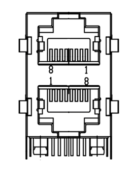
RS232/485
Connector: 8P8C RJ45
RJ45, 8 poles 8 connections
1 Motor B2 2 Motor B1 3 Motor A2 4 Motor A1 5 Limit 1 6 Limit 2 7 Thermocouple negative 8 Thermocouple positive 9 GND
10 11 12 13 RTD B2 14 RTD B1 15 RTD A
Encoder
Front panel
Same ideas smd3
See mech of ds for smd4 connectors etc.
All the text about IMO connectors goes, as smd4 does not have them. see rb for pinouts
power - per smd3 manual with changes: fixed 48 v per datasheet, statement about max 67 goes because smd4 is for fixed 48v, blue info bit goes.
The rest just copy per smd3, but with substitute the new connectors
No thermocouple connector as now in motor connector, so move that section there
There are new connectors; 2 x rj45 for rs232/485 and 1 x rj45 for ethernet. Leave template sections for now.
Motor wiring; all change, leave empty section for now
Lead identification stuff remains same, as does wiring, cable stripping beads, cable requirements etc, rb to edit once template is in
Rear Panel
Power
x
Motor
x
I/O
x
Motor wiring
Overview
x
Lead identification
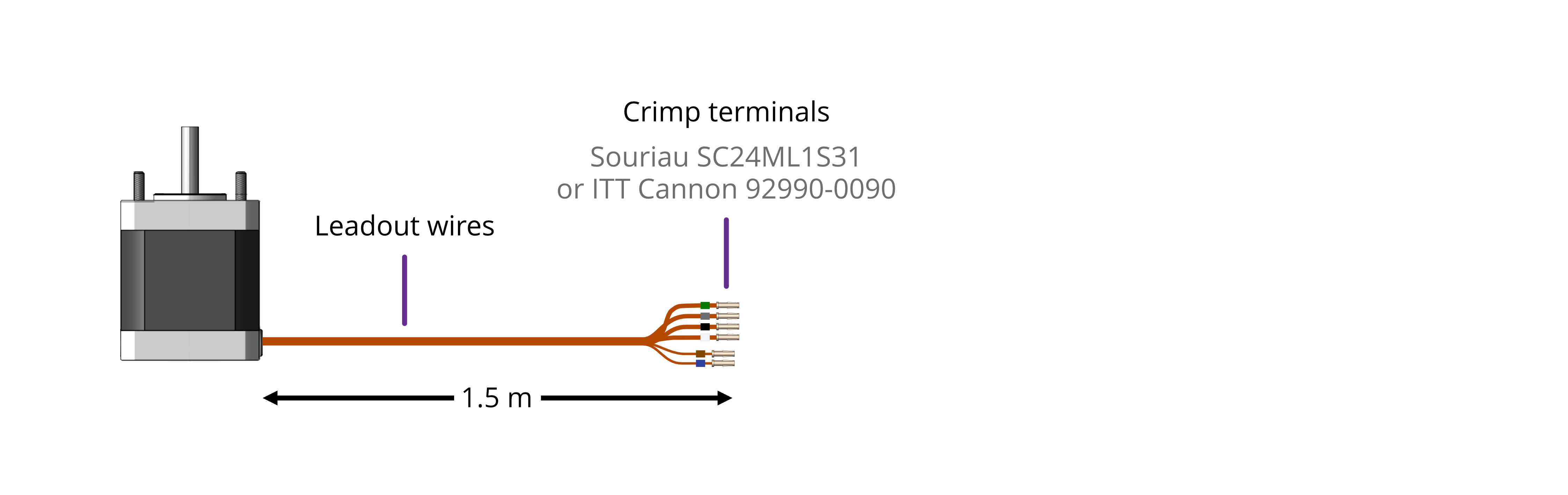
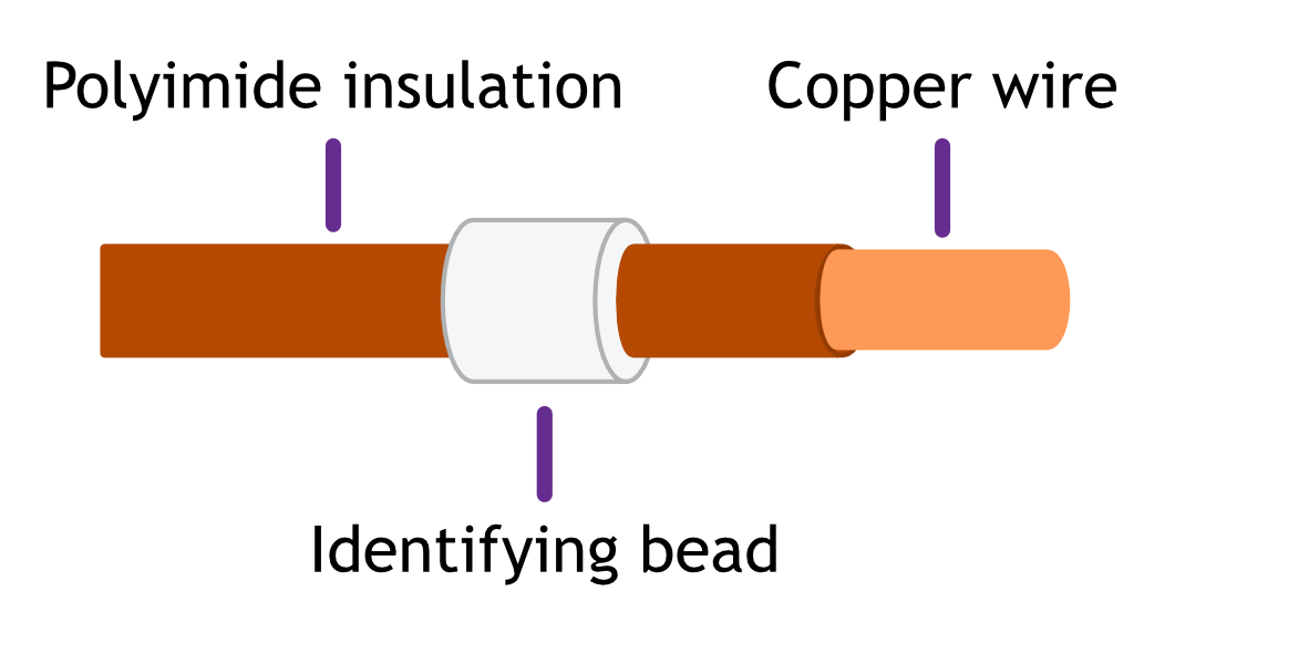
The motor leadout wires are self-coloured polyimide film-wrapped, silver-plated OFHC solid copper and each is fitted with a 1.5 mm crimp socket terminal. They are supplied fitted with UHV compatible coloured glass beads for identification. The phase leadout wires are much thicker than the thermocouple leadouts. The leadout wires of each phase should be twisted together.
| Motors equiped with a Thermocouple: | Motors equiped with an RTD: |
 |
|
If the identification beads have been removed, the wires can be identified using an inexpensive multimeter, and a magnet. The multimeter must be capable of measuring resistance with a resolution of about 1 ohm.
|
Thermocouple Leadouts The thermocouple wires are much thinner than the phase leads, and there are two of them. If three wires are present, the motor has an RTD installed, see below for details. The thermocouple is insulated from the rest of the motor. |
|
|||||||||
|
RTD Leadouts As per the thermocouple leads, but three instead of two leads. These must be identified by resistance; one pair of wires are connected at the motor end. These will measure a few ohms depending on cable length and are the ‘B1’ and ‘B2’ connections, which are interchangeable. The remaining wire is the ‘A’ connection and should measure around 100 ohms to either ‘B1’ or ‘B2’. |
|
||||||||||||
Phase leadouts
These are the four thicker leadouts. Identify the two motor phases by their resistance, which will be in the range of 3 to 15 ohms, depending on the motor type. There is no electrical connection between the two phases, to the thermocouple/RTD or the case of the motor. Most of the resistance is in the windings of the motor and is virtually unaffected by shortening of the leads. Connect each phase to the appropriate drive terminals. The resistance of the wires from the feedthrough to the drive must be less than a few ohms.
Note regarding reversal of rotation
Upon completion of wiring, there is a 50 % probability that the direction of rotation will be reversed from the desired or conventional sense. To rectify this, exchange the connections to one of the phases. For example, locate the Phase A + and Phase A – connections, and swap them around. This can be done on air or vacuum side while the chamber is still open.
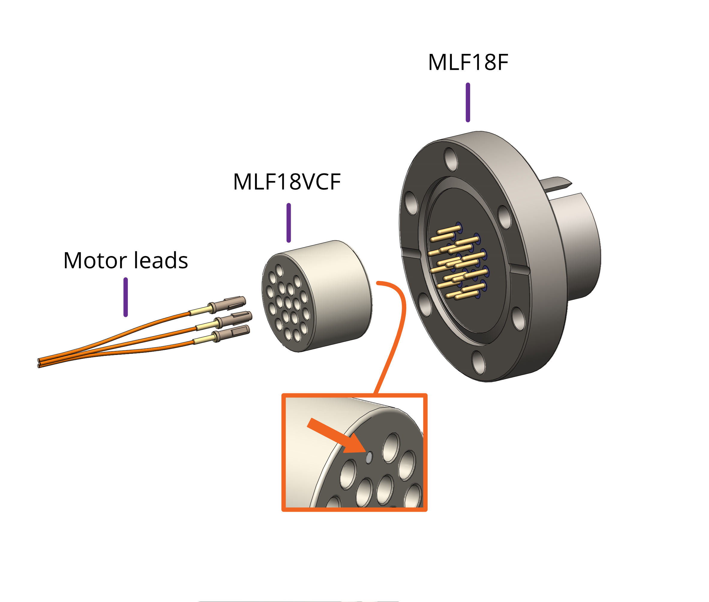
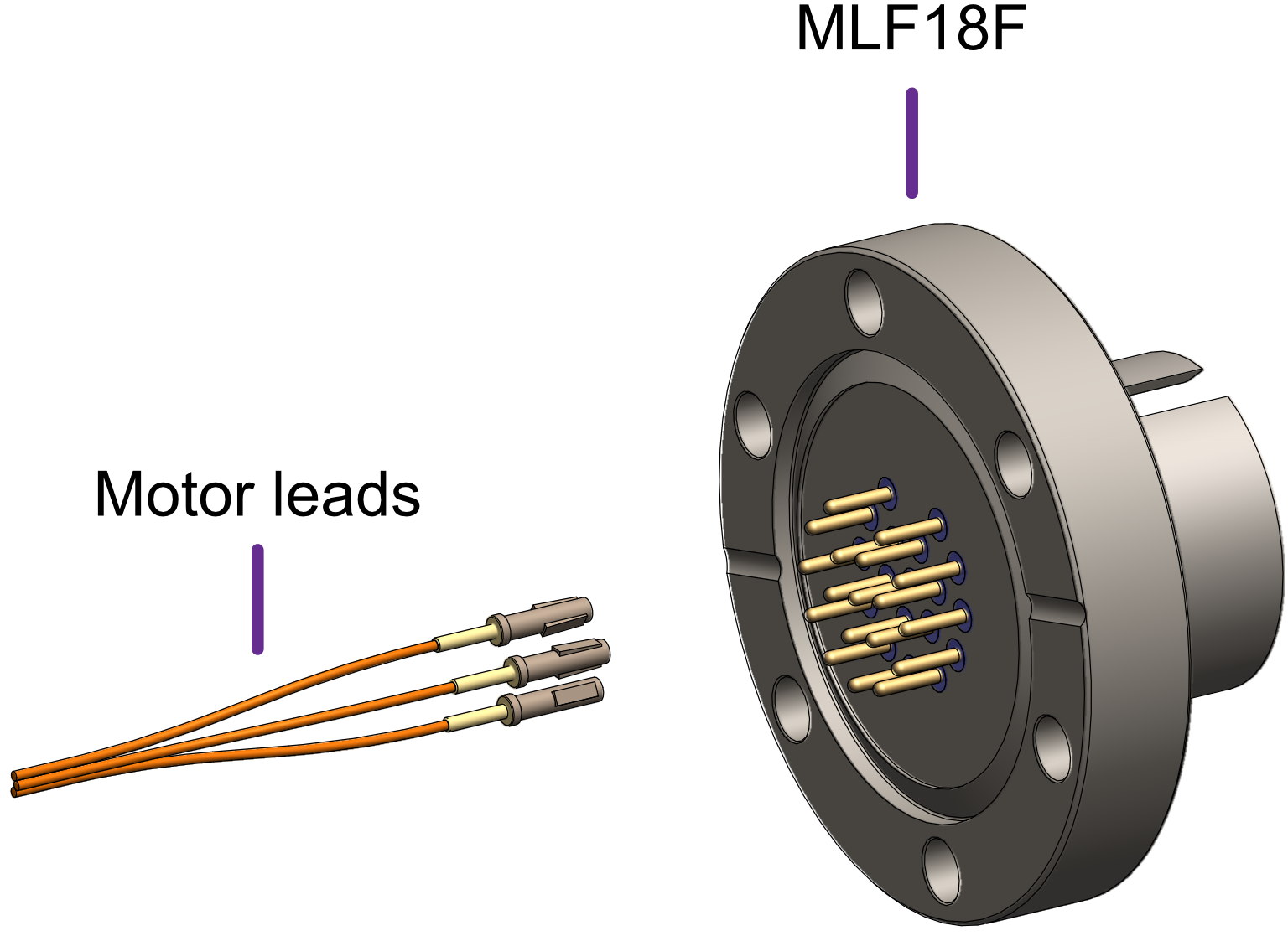
Wiring motor to the vacuum feedthrough
The MLF18F feedthrough has 18 x 1.5 mm gold-plated feedthrough pins and is suitable for up to three motors fitted with thermocouples or up to two motors fitted with 3-wire RTDs. An internal bakeable connector, MLF18VCF, is available into which the crimp terminals on the motor leads are inserted. This significantly reduces the risk of short-circuits and makes the installation more convenient.
| Using the MLF18F feedthrough and MLF18VCF vacuum side connector: | Alternatively, plug crimps directly onto the feedthrough pins of the MLF18F: |
|
|
|
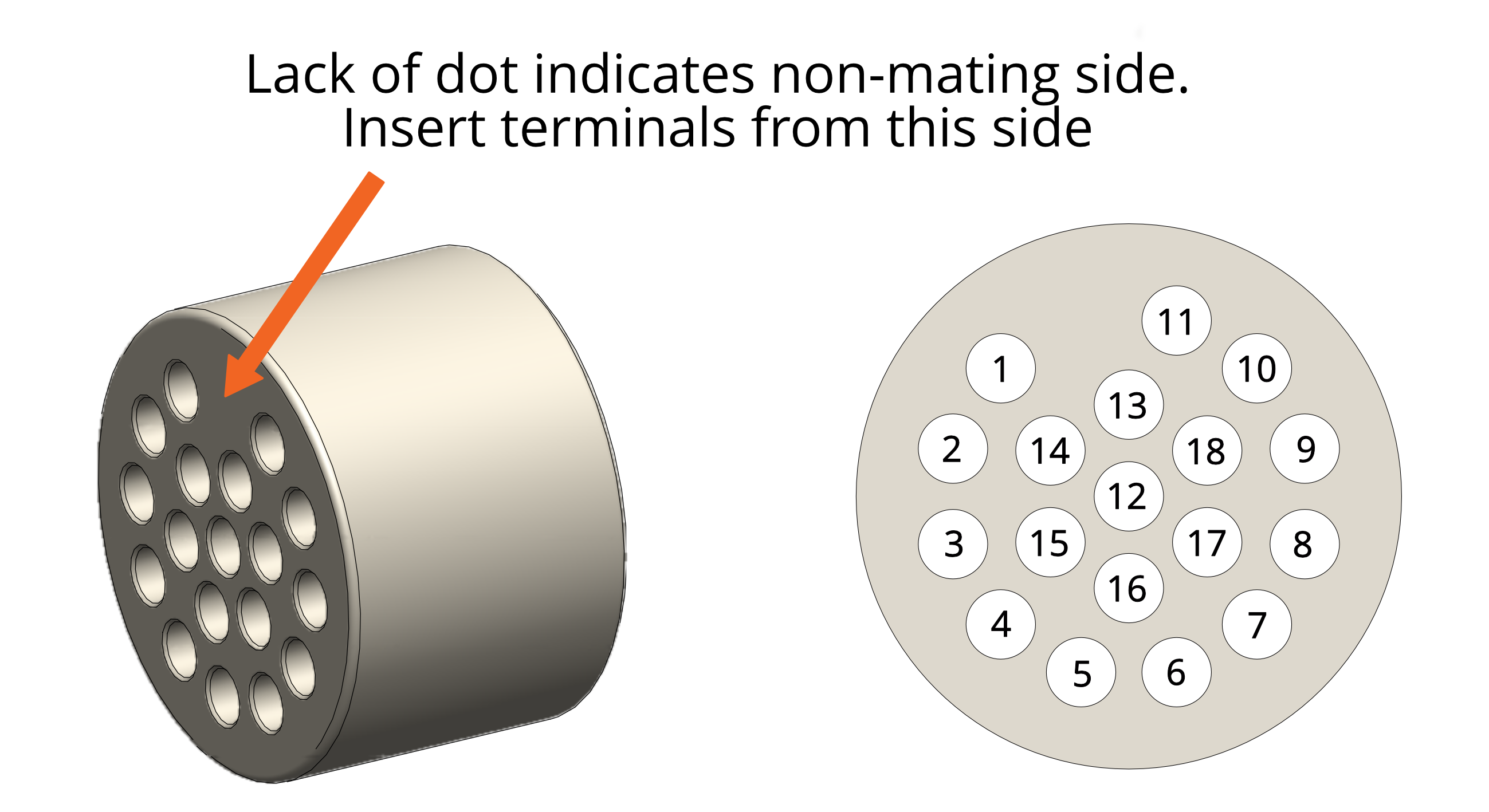
| Mating side identified by dot. Motor lead terminals should be inserted in the other side. |
| Standard pinout for the MLF18VCF | |||||||||||||||||||||||||||||||||||||||||
| The illustration below shows the view into the non-mating side of the connector, into which the motor leads should be inserted, as shown below. | |||||||||||||||||||||||||||||||||||||||||
|
 |
||||||||||||||||||||||||||||||||||||||||
Using other feedthroughs
AML stepper motors can be ordered with either a K-Type thermocouple, or 3-wire PT100 RTD. The former requires 6 pins, and the latter 7 pins.
When using motors installed with a thermocouple, it is not necessary to use a thermocouple vacuum feedthrough or extension wires, as the error introduced by incompatible feedthrough material is usually less than 5 °C and the temperature measurement is not required to be very precise.
| Preparation of motor leadouts for connection to other feedthroughs | |
|
If making custom terminations for the motor leads, the installed crimps must be removed, and the wire ends stripped of insulation. Standard motors are fitted with Polyimide film-wrapped leads (illustrated below), and radiation-hard motors are fitted with polyimide enamelled leads.
Polyimide is strong, flexible and abrasion-resistant and therefore difficult to strip. The simplest method of stripping polyimide film is to cut a ring with a sharp knife and withdraw the cylinder of insulation over the end of the wire. Be careful not to mark the conductor surface with the knife. Strip the enamelled radiation-hard leads by scraping with a sharp knife. Either type of lead may be stripped with a suitable high-speed rotary stripper. Do not use a thermal stripper. |
 |
Wiring between drive and vacuum feedthrough
AML supply the MLF18SMD3 lead for use with the SMD3 and MLF18F feedthrough. It allows connection of up to two drives and motors installed in one vacuum chamber. Alternatively, AML supply the MLF18AC; which can be used to make custom leads to mate with the MLF18F feedthrough. This is supplied with a kit that includes the crimps and a grounding lead attached to the connector shell, as well as instructions for their use. The SMD3 is supplied with a kit of matching connectors.
Leads between the MLF18AC and SMD3 should be assembled according to the following guidance for safe, reliable operation and continued compliance with EMC standards.
Cable requirements
- Quantity of cores as required; (one motor requires 6 cores when fitted with a thermocouple, or 7 if fitted with an RTD). The cable must be screened. A foil screen plus drain wire is acceptable; a foil plus braid screen is better.
- The screen must be connected via as short a wire as possible to pin 1, ‘GND’ of the motor connector, using insulated wire.
- Rated voltage >= 300 V rms
- Rated current > 1.5 A rms
- Cable cores must be twisted together in pairs, using one pair per phase, one pair for the thermocouple, and a group of three for the RTD. This reduces radiated emissions from the cable and improves immunity of the RTD and thermocouple signals to the motor.
- Maximum cable length is limited by round trip resistance, which should be less than a few ohms. Review cable manufacturers data to obtain this figure.
Wiring up to the MLF18AC airside connector
The MLF18AC is supplied with comprehensive instructions detailing correct usage of the connector. The pinout to match with the standard MLF18F + MLF18VCF pinning described in section Motor wiring is shown below. Note that the illustration shows the MLF18AC looking into the non-mating side of the connector, i.e. the side into which crimps are inserted.
|
Looking into the non-mating face of the MLF18AC, into which crimps are inserted |
||||||||||||||||||||||||||||||||||||||||
|