Operation
copy everything in from smd3 manual, with these changes, then will edit from there:
operating modes; remote now has many more options than just usb, to discuss how to represent that
Getting started
The quickest way to get started with the SMD4 having completed wiring up according to the previous chapter is to install the SMD4 software on your PC (see section 6), power on the SMD4 and connect it with the USB lead to the PC. The SMD4 software provides an intuitive and easy way to configure and evaluate the features of the SMD4 described in the remainder of this section.
This section discusses the various operational modes and configuration options available. The SMD4 software provides easy access to these functions, as well as help text describing each. If communicating with the SMD4 directly, using a terminal program or your own software, see section 7 which lists the commands available.
Operating modes
ThereThe areproduct fivehas several operating modes:
Remote
The modes are:
All setup (including mode selection) must be performed using thevia remote interface.interface
Joystick - Control of motor via a joystick
of
motorIdealvia forindustry basic movement during commissioning; press for onestandard step, pressdirection andenable holdinterface
Step/Direction
Opto-isolated step and direction; configurable rising or rising/falling edge; up to 256x interpolation.
Bake
Heats the motor by energising both phases and holding the motor stationary, regulating thephase current to achieveheat amotor setpoint(while temperature.keeping Usedit stationary) to drive off adsorbed moisturegasses
in the motor.
Step/Direction triggered velocity
Start/stop using step signal, Positive/negative movement according to direction signal; configurable velocity profile.
Home
Home mode drives the motor to the positive or negative limit switch.
INFORMATION: Mode can be changed only when the motor is not performing any movement. This can be verified by checking the standby flag, which is returned in a status register by the SMD4 on every communication, see section 7.2. The firmware prevents mode change when the standby flag is not set.
In the case of Step/Direction mode, it is the responsibility of the external controller to perform any final activities, such as coming to a stop, before changing the mode.
Step/DirectionRemote
Motor movement is controlled by externally supplied step and direction signals. The SMD4 can be configured to step on the rising or rising and falling edges, which halves the step clock rate.
Note that the external enable fault is non-latching when in step direction mode; once the external enable state is restored, or the external enable setting is changed to false, normal operation will resume immediately without the need to clear it. See also section X3-I/O.
Step input
Direction input
Both
Rising only
Meaning
Rising
Step
Step
Low
Positive
Falling
Step
High
Negative
Steps are generated according to the current resolution. For example, with the edge setting on rising only, and microstep resolution set to 128, each rising edge on the step input will generate a single 1/128th step in the positive direction.
A step interpolation option is available; when enabled, the step input behaves as it would with the current resolution, except that each step input is interpolated to 256 microsteps. This is done by evaluating the rate at which steps arrive and timing 256 microsteps within the step to step period. This gives all the benefits of microstepping at high resolution while minimising the input clock rate.
The relationship between step input, resolution and actual step frequency is given below:
Motor Step frequency [Hz] = (Step input [Hz] / Resolution)
INFORMATION: Stopping on fractional stepsThere is no mechanism to prevent theCommand motor from stopping on fractional steps as there is in all other modes.Stopping on fractional steps will result in the motor temperature rising much faster than it otherwise would and is generally not suitable for vacuum applications. Therefore, configure the external step generator to meet this criteria.
INFORMATION: Preparation before switching out of Step/Direction modeWhen changing to another mode from Step/Direction mode, ensure that any movement being commanded via Step/Direction interface has completed before switching.
Step/Direction triggered velocity
This mode works the same as joystick continuous mode, except that the positive and negative inputs that would normally be suppliedmovements via the joystickremote inputinterface. areComprehensive insteadcontrol generated from the step and direction inputs:
Step input
Direction input
Meaning
Meaning
Rising
Triggers start / stop
Low
Positive
Falling
No action
High
Negative
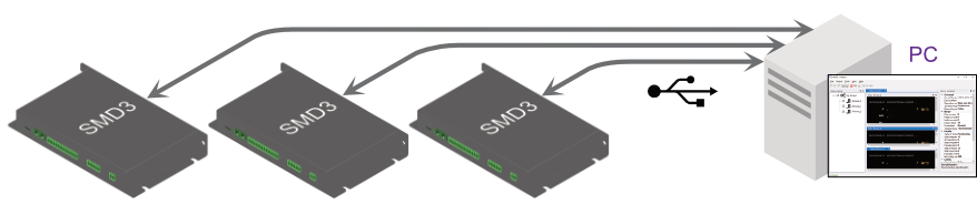
Remote
Remote mode is used to performof all aspects of configurationmotor andmovement. mayOther alsofunctions beare usedexecuted tofrom controlremote mode, for example homing, in which the motor movementmoves directly.until a limit switch is hit, serving as a reference for future movements.
The easiest way to douse soremote mode is usingwith the supplied SMD4AML Device Control software, which allows one or more SMD4 units to be combined into a system and controlled individually or as a group. This makes it easy to apply the same configuration to multiple devices, for example.
Alternatively, the SMD4 may be controlled via a simple terminal application or your own software. A C# API is available to speed up development of your own applications. The remote interface is described in section USB interface.
Homing function
Homing drives the motor to the positive or negative limit switch. The motor first moves toward the limit switch using the existing movement profile. On the limit switch being triggered, the step frequency is halved, and the motor reversed until the limit switch is not triggered. Finally, the motor moves toward the limit switch at a step frequency of 30 Hz until the limit switch is triggered.
INFORMATION: Limitations of limits
Limit switches are not latching, i.e. as soon as a limit input becomes not triggered, for example if the mechanism is able to first actuate a limit switch and then continue moving past it until the limit switch is no longer actuated, then the SMD4 will be unaware of this and will continue to drive the motor if commanded.
Limits switches and cams are normally arranged such that the limit switch is triggered from the desired point up to and including the point at which the mechanical limit of the mechanism is encountered.
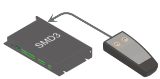
Joystick
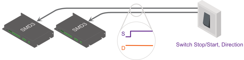
Basic motor movements may be commanded via a two-button joystick connected to front panel connector, ‘X6–Joystick’.connector. AML supply the SMD4 Joystick, part number ‘SMD4JOY’ for this purpose. OnOptionally, on connection, the SMD4 automatically switches to joystick mode, and reverts to the previous mode on removal of the joystick. This behaviorbehaviour can be disabled if required. Section X6-Joystick discusses the electrical aspects of the joystick input, including details for building a custom joystick.
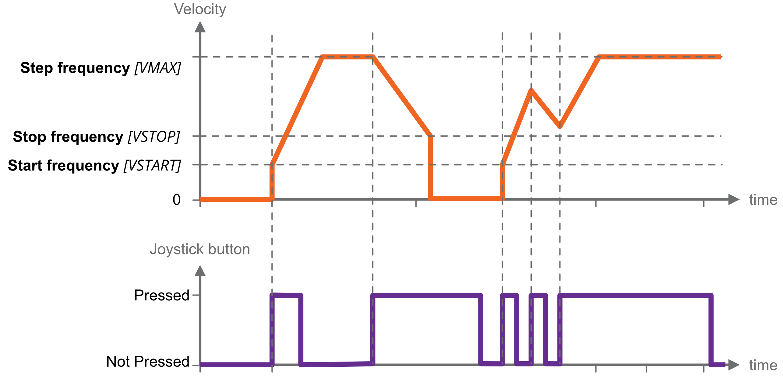
There are two joystick modes; both operate using velocity mode (see section Velocity and Positioning Mode for details) in which a profile, including acceleration, deceleration and target frequency are programmed, then motor movement is triggered by the joystick.
|
Continous
|
Motor accelerates toward target frequency on joystick key down. Continuing to hold the key down has no further effect.
On releasing and pressing the same key again, the motor decelerates toward a stop.
On pressing the alternate direction key, motor first decelerates to a stop before accelerating toward target frequency in the other direction.
If the motor has not yet come to a stop, and the same key is pressed again, the motor will once more accelerate towards target frequency, as illustrated left. |
|
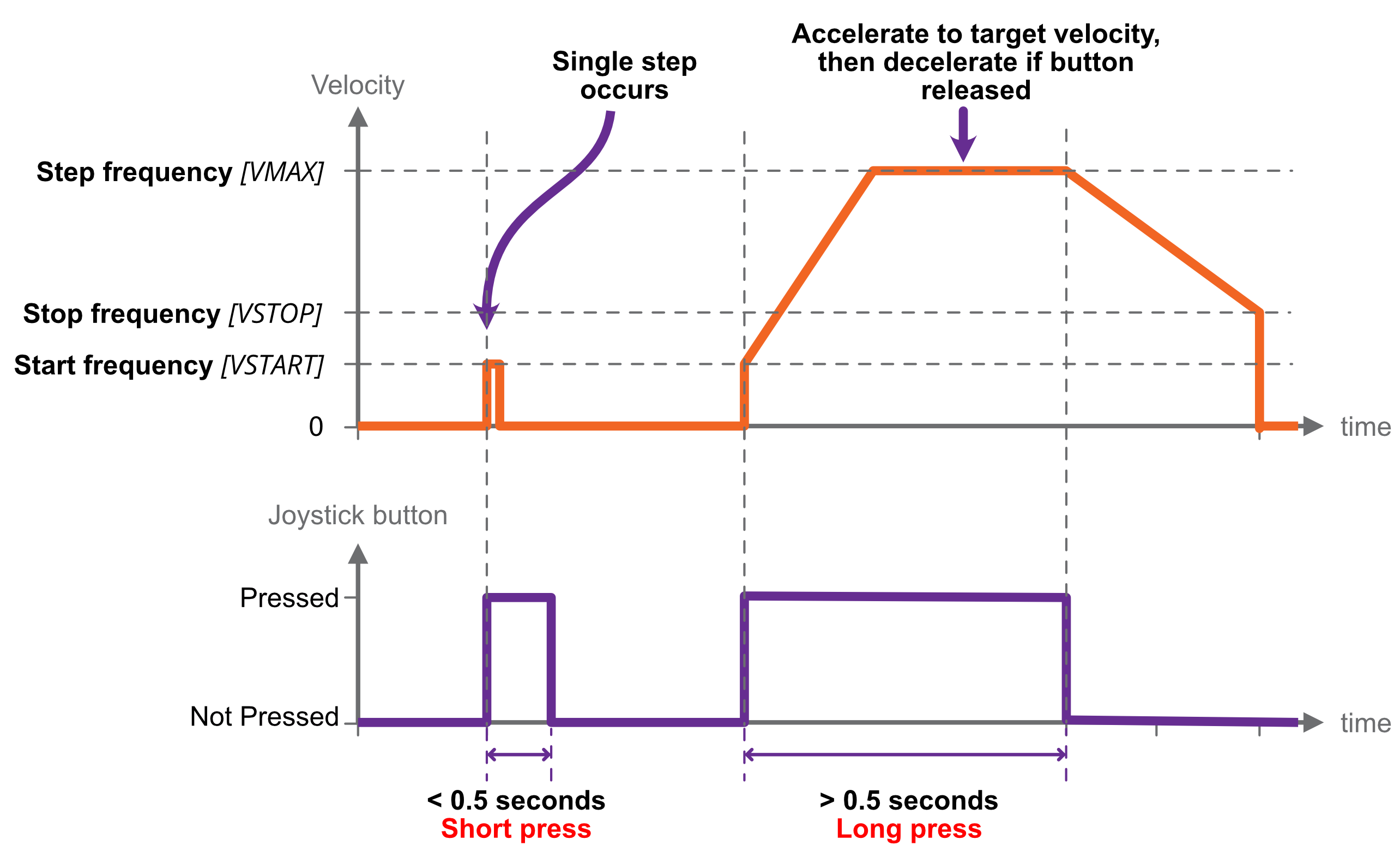
Single step
|
A short button press (< 0.5 s) causes a single step in the commanded direction. This is useful for precise positioning.
A long press (> 0.5 s) triggers acceleration toward the target frequency, while the button continues to be pressed.
Releasing the button causes the motor to decelerate toward a stop.
If the button is pressed while the motor is still decelerating, the motor once more accelerates toward target frequency for as long as the button is held. |
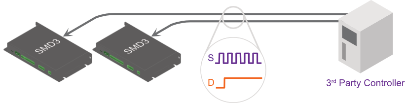
BakeStep/Direction
BakeMotor movement is controlled by externally supplied step and direction signals. There are two sub modes, normal and triggered.
Normal mode
The SMD4 can be configured to step on the rising or rising and falling edges, which halves the step clock rate.
The external enable fault is non-latching when in step direction mode; once the external enable state is restored, or the external enable setting is changed to false, normal operation will resume immediately without the need to clear it.
Step input
Direction input
Both
Rising only
Meaning
Rising
Step
Step
Low
Positive
Falling
Step
High
Negative
Steps are generated according to the current resolution. For example, with the edge setting on rising only, and microstep resolution set to 128, each rising edge on the step input will generate a single 1/128th step.
A step interpolation option is available; when enabled, the step input behaves as it would with the current resolution, except that each step input is interpolated to 256 microsteps. This is done by evaluating the rate at which steps arrive and timing 256 microsteps within the step to step period. This gives all the benefits of microstepping at high resolution while minimising the input clock rate.
The relationship between step input, resolution and actual step frequency is given below:
Motor Step frequency [Hz] = (Step input [Hz] / Resolution)
INFORMATION: Stopping on fractional steps
There is no mechanism to prevent the motor from stopping on fractional steps as there is in all other modes.
Stopping on fractional steps will result in the motor temperature rising much faster than it otherwise would and is generally not suitable for vacuum applications. Therefore, configure the external step generator to meet this criteria.
INFORMATION: Preparation before switching out of Step/Direction mode
When changing to another mode regulatesfrom phaseStep/Direction mode, ensure that any movement being commanded via Step/Direction interface has completed, and that the motor is at a full step position before switching.
Triggered mode
This mode works the same as joystick continuous mode, except that the positive and negative inputs that would normally be supplied via the joystick input are instead generated from the step and direction inputs:
Step input
Direction input
Meaning
Meaning
Rising
Triggers start / stop
Low
Positive
Falling
No action
High
Negative
In the case of Step/Direction mode, it is the responsibility of the external controller to perform any final activities, such as coming to a stop, before changing the mode.
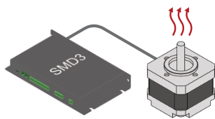
Bake
Heats the motor by energising both phases and holding the motor stationary, regulating the current to heat the motor toachieve a specified setpoint temperature. TheUsed motorto isdrive heldoff stationary.adsorbed moisture in the motor.
Before engaging bake mode, set the target bake temperature. When in bake mode, the green status indicator will flash briefly at intervals as a reminder that this mode is active.
Home
Home mode drives the motor to the positive or negative limit switch. The motor first moves toward the limit switch using the existing movement profile. On the limit switch being triggered, the step frequency is halved, and the motor reversed until the limit switch is not triggered. Finally, the motor moves toward the limit switch at a step frequency of 30 Hz until the limit switch is triggered.
INFORMATION: Limitations of limitsLimit switches are not latching, i.e. as soon as a limit input becomes not triggered, for example if the mechanism is able to first actuate a limit switch and then continue moving past it until the limit switch is no longer actuated, then the SMD4 will be unaware of this and will continue to drive the motor if commanded.
Limits switches and cams are normally arranged such that the limit switch is triggered from the desired point up to and including the point at which the mechanical limit of the mechanism is encountered.
General concepts
User interface
In general, all control and configuration of the SMD4 is performed via the remote interface. The following functions and indications are available locally on the SMD4:
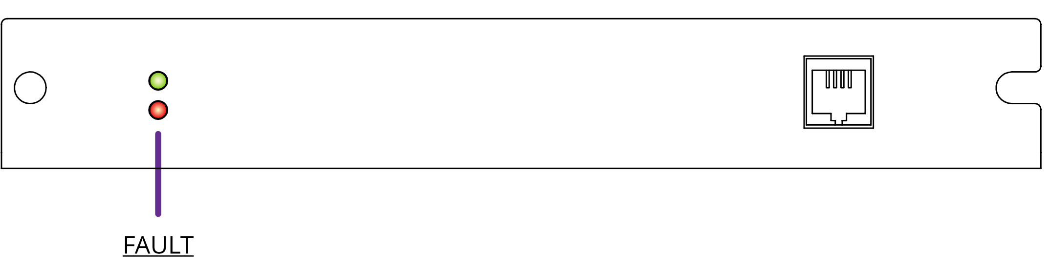
- Basic status information, via front panel green and red indicators. Green signifies power on and normal operation, red a fault. See section Faults. The green indicator also blinks briefly when the operating mode is changed.
- Joystick control – plug a joystick into the front panel joystick connection, and basic movements may be performed according to the current configuration. See section Joystick.
- Step/Direction interface; if in this mode, the motor may be controlled via signals supplied on the I/O port. See section Step / Direction.
- Fault output and fault reset input on
‘X3 –the I/O’O connector – An open collector fault output is set when a fault occurs. The fault state can be reset by pulling the fault reset pin to the ‘GND’ pin of‘X3 –the I/O’.O connector. See section Faults.
Persistence of settings
All changes made to the configuration via the remote interface are volatile (i.e. not retained on power cycling) unless the store command is executed before powering off. The AML SMD4Device Control software warns you of this when closing the application, but if writing a custom application to control the SMD4, your application must handle this if settings are to be persisted.
The SMD4 will always load the last stored settings on power on, or if the store command has not been previously used, defaults are loaded as per section Command Reference. If settings become corrupted, for example the write endurance of the memory in which the settings are stored is exceeded, the SMD4 loads defaults as identified above, and a fault indication is given, see section Faults.
INFORMATION: Write endurance
The memory in which settings are stored has an endurance of about 1 Million write cycles. Only use the store command when necessary, for example, take care that your application does not perform multiple redundant store commands.
Motor current
Three values may be set for motor current; acceleration current, run current and hold current.
|
|
Applies when |
|
Acceleration |
Motor is running but not at target frequency, i.e. during acceleration and deceleration. This allows you to set a higher current during acceleration (to overcome inertia of a large load, for example) and revert to a lower current once the load is moving, thus reducing motor power dissipation and extending run time. If you do not wish to use this feature, simply set acceleration current to equal run current. |
|
Run |
Motor has reached target frequency. |
|
Hold |
Motor is stopped and is only necessary where the motor detent torque is not enough to prevent undesirable movement of the load. The cost of using hold current is increased motor temperature under vacuum. Therefore, where possible, mechanisms should be designed to be statically balanced, and the hold current should be set to 0. |
When the motor starts moving, acceleration current is applied immediately. When the motor stops after the deceleration, two additional states must be traversed before the acceleration current is reduced to hold current, first, a configurable delay during which acceleration current continues to be applied (called ‘standstill’ state), followed by a configurable delay during which acceleration current is reduced to hold current (called ‘going to standby’ state).
Run current must be set equal to or smaller than acceleration current. This is enforced by the SMD4; if a change to run current makes it greater than the acceleration current, the acceleration current is automatically adjusted to be equal to run current.
Standstill
Period after motor has stopped during which acceleration current is still applied. Adjustable between about 0 and 5.57 seconds using the ‘Power down delay’ setting [PDDEL]. Set to the minimum value suitable for your application to minimise heat generated.
Going to standby
Period during which acceleration current is gradually reduced to hold current. This smooth transition avoids a motor jerk on power down. Motor current is not continuously adjustable, instead being one of 31 discrete values from 0 to 1.044 A rms. Therefore, the current ramps down in steps. The step size may be set between 0 (instant power down) and 327 ms using the ‘Current reduction delay’ setting [IHD]. Set to the minimum value suitable for your application to minimise heat generated.
The name of each setting in the following illustrations matches that used in the software. The command mnemonic, for use if programming the SMD4 via the remote interface (see section USB Interface), is given in square brackets.
|
|
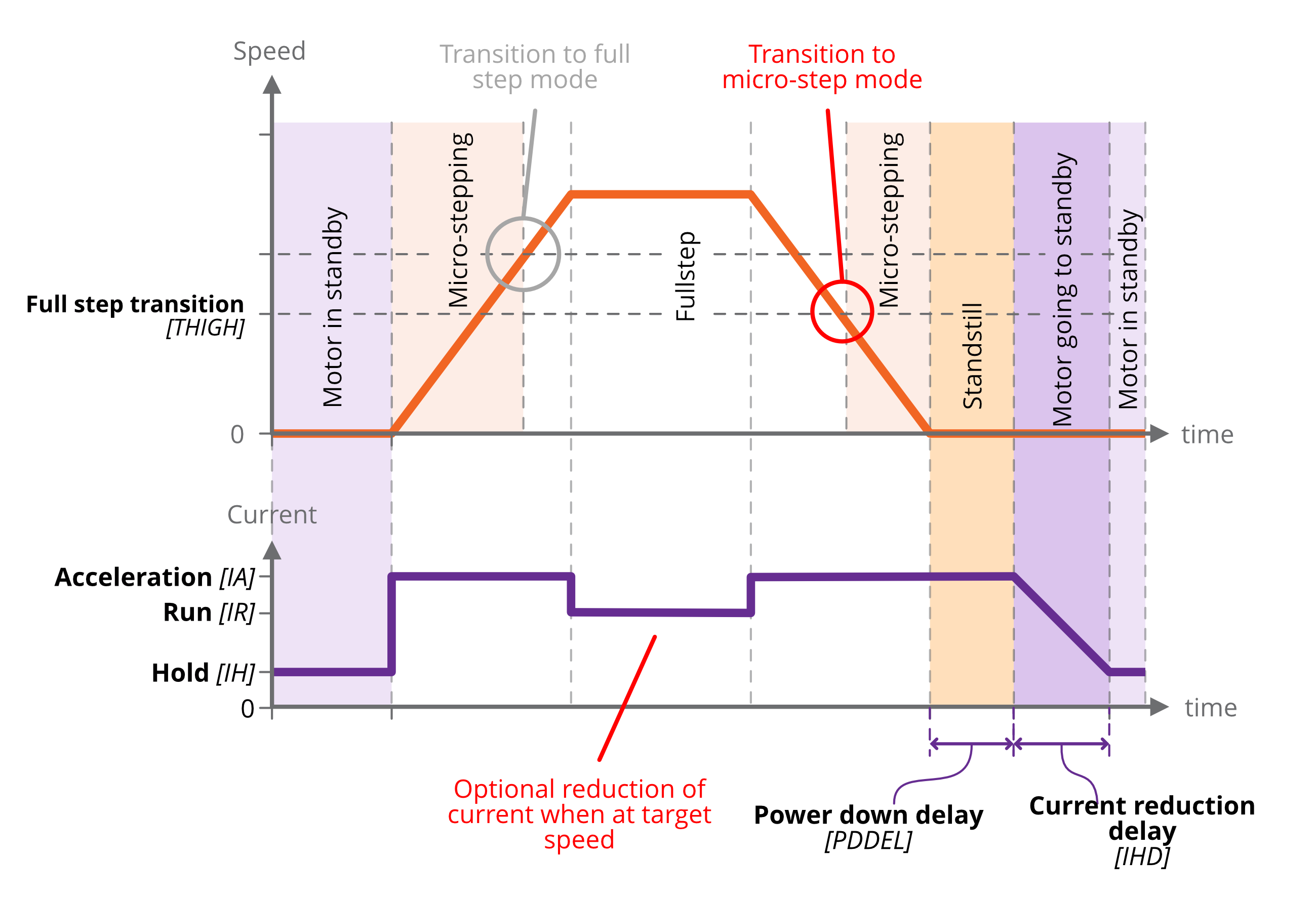
Figure 1 - Motor current and speed
Microstepping
Microstepping is applicable at low step frequencies (typically < 500 Hz) and helps reduce motor resonances resulting in smoother operation. In non-vacuum applications, it is also used to achieve increased positioning resolution, however, it requires energising both motor phases continuously even when the motor is stopped to maintain position, resulting in unacceptable levels of temperature rise in the motor in vacuum applications. Instead, mechanisms are designed to achieve the required positioning resolution with appropriate gearing.
Microstepping is not helpful at higher step rates, therefore, the SMD4 automatically switches between microstepping at low speeds and full step at high speeds. The transition point from full step to microstep is configurable, as illustrated in Figure 1. Hysteresis is applied to this value resulting in the transition in the opposite direction (from microstep to full step) being at a slightly higher frequency, as illustrated above. Note that you cannot explicitly set the transition to full step point, only the transition from full step to microstep. The other transition is calculated automatically.
The resolution to use during microstepping is configurable, via the microstep resolution setting [RES]. Choices are 8, 16, 32, 64, 128 and 256. In all modes except for step/direction, the motor is only stopped in full-step positions. Microstepping is used exclusively for the purpose of smoothing the transition between steps.
The accuracy with which motor profile (acceleration, deceleration, etc.) settings may be made depends on the microstepping resolution; the maximum microstep resolution of 256 offers the greatest accuracy for these settings.
Freewheel mode
Freewheel mode refers to how the motor is configured when it is at standstill and zero hold current is set. There are three choices:
-
Use freewheel for minimum holding torque, which allows the motor shaft to be moved freely.
-
Phases shorted for maximum holding torque with zero power applied to the motor (and so no heat generated in the motor).
-
Normal offers some minimal amount of holding torque as a result of the phases still being connected to the driver circuitry.
Velocity and Positioning mode
All modes except step/direction fundamentally use the hardware of the SMD4 in one of two ways:
- Velocity mode. Motor is accelerated to a target velocity in a specified direction (Positive or Negative), which may be maintained indefinitely. On stopping, the SMD4 decelerates according to the configured profile and stops in a full step position.
- Positioning mode. Motor is driven toward a chosen position, determined by an internal step counter and a relative or absolute step count position. The motor starts by accelerating towards the target velocity, then as the target position is approached begins to decelerate before coming to a stop at the target position. Position can be specified in full steps only.
Step/direction triggered velocity mode uses velocity mode internally and joystick mode uses a combination of velocity and positioning mode. In remote mode, velocity and positioning mode must be selected with the appropriate command.
Initiating movement
In remote mode, movement is started via a run command and stopped via stop command. Movement cannot begin spontaneously as a result of changing a setting, for example. Direction is specified as positive, which results in the position counter incrementing, or negative which results in the position counter decrementing.
In all other modes, motor movement is determined by an external stimulus, for example, a joystick button press in joystick mode, or an edge on the step input in step/direction mode.
Monitoring the motor
Motor temperature, speed and position may be queried using remote interface commands.
INFORMATION: Motor control is open loop, therefore quantities such as position and velocity are determined from internal counters in the SMD4. These cannot be relied upon in certain circumstances, such as if the motor is stalled, or misses steps due to improper configuration.
Enable input
An enable input EN (X3 - I/O) is present as part of the SDE interface, but the enable signal may be used in any mode. The motor is enabled when high and disabled (all motor movement inhibited) when low.
The enable input is ‘gated’ by an external enable setting; when enabled, the behaviour described above applies. When disabled, the enable input is treated as if it was true, regardless of the actual state. This allows the user to decide whether the enable input is used or not.
When the enable input is not used, then the SMD4 is responsible for enabling the motor as required, consistent with any other requirement described in this document.
|
Enable input |
||
|
|
Setting enabled |
Setting disabled |
|
Low |
Motor disabled |
Motor enabled |
|
High |
Motor enabled |
Motor enabled |
Motor configuration
Temperature sensor selection
AML motors can be supplied with either a K-Type thermocouple or PT100 RTD temperature sensor. Ensure the sensor is connected to the thermocouple (X4 - Thermocouple) or RTD (X3input –on I/O)the input,motor connector, and make the appropriate selection. The temperature sensor select command [TSEL] allows selection between thermocouple and RTD.
INFORMATION: The motor is disabled if the temperature sensor is misconnected, faulty or the temperature measurement exceeds 190 °C in order to protect the motor from possible damage to the insulation material.
Check that the motor temperature sensor selection matches that of your motor.
When using a thermocouple, avoid significant temperature gradients across the thermocouple leads and connector on the SMD4.
Profile configuration
This section is concerned with configuring dynamic properties of motor movement. The profile settings apply to all modes except for step/direction mode. Tuning of these parameters is required to optimise motor performance in your application, and is necessary to engage positioning or velocity mode.
The name of each setting in the following illustrations matches that used in the software. The command mnemonic, for use if programming the SMD4 via the remote interface (see section USB Interface), is given in square brackets.
|
|
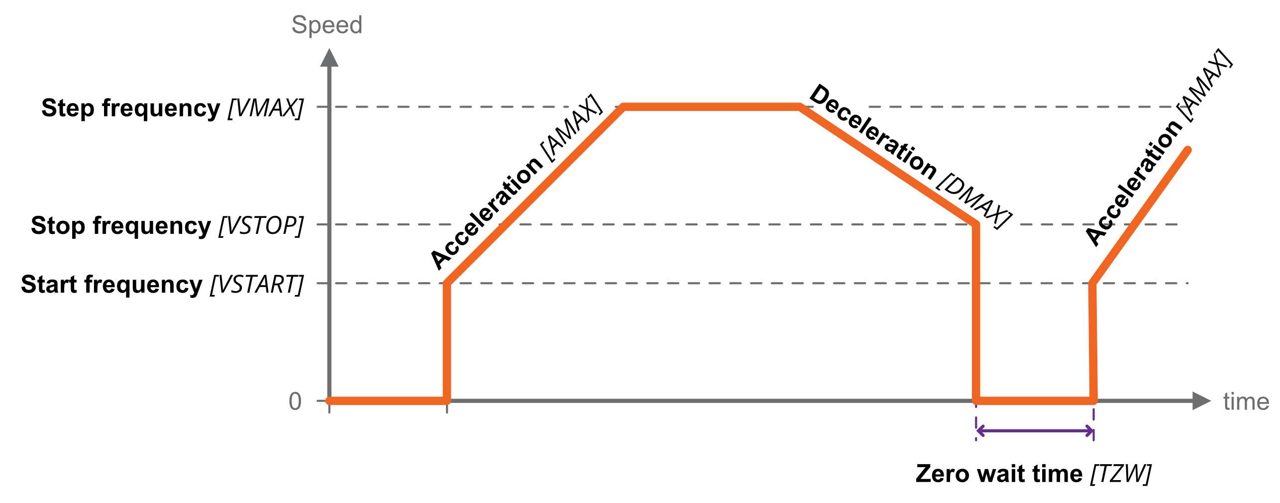
Start and stop frequency
The start frequency is the initial step rate, and helps to allow the motor to overcome inertia and start moving smoothly; if start frequency were zero, the duration of the initial few steps might be long enough that the motor would overcome inertia on the first step, then effectively stop for a period of time, then have to overcome inertia once more for the second step, and so on, until the steps were frequent enough that the motor remains moving.
Stop frequency is the counterpart setting which determines the frequency for the last step. Both are specified in Hz, or steps per second.
Start frequency must be set equal to or smaller than stop frequency. This is enforced by the SMD4; if a change to the stop frequency makes it smaller than the start frequency, start frequency is automatically adjusted to be equal to stop frequency.
Start frequency and Stop frequency must be set equal to or smaller than Step frequency. The SMD4 will not force Start and Stop frequency to match Step frequency if either Start or Stop frequency are smaller than Step frequency.
Acceleration and deceleration
The SMD4 implements linear acceleration and deceleration ramps; velocity ramps up between the start frequency and the step frequency, and down linearly between the step frequency and stop frequency. Both are specified in Hz-1, or steps per second per second.
Changing direction
When using higher values for the start and stop frequency, a subsequent move in the opposite direction would result in a jerk equal to start frequency + stop frequency. The motor may not be able to follow this. The zero wait time setting [TZW] can be used to introduce a short delay between the two and eliminate the jerk as illustrated above.
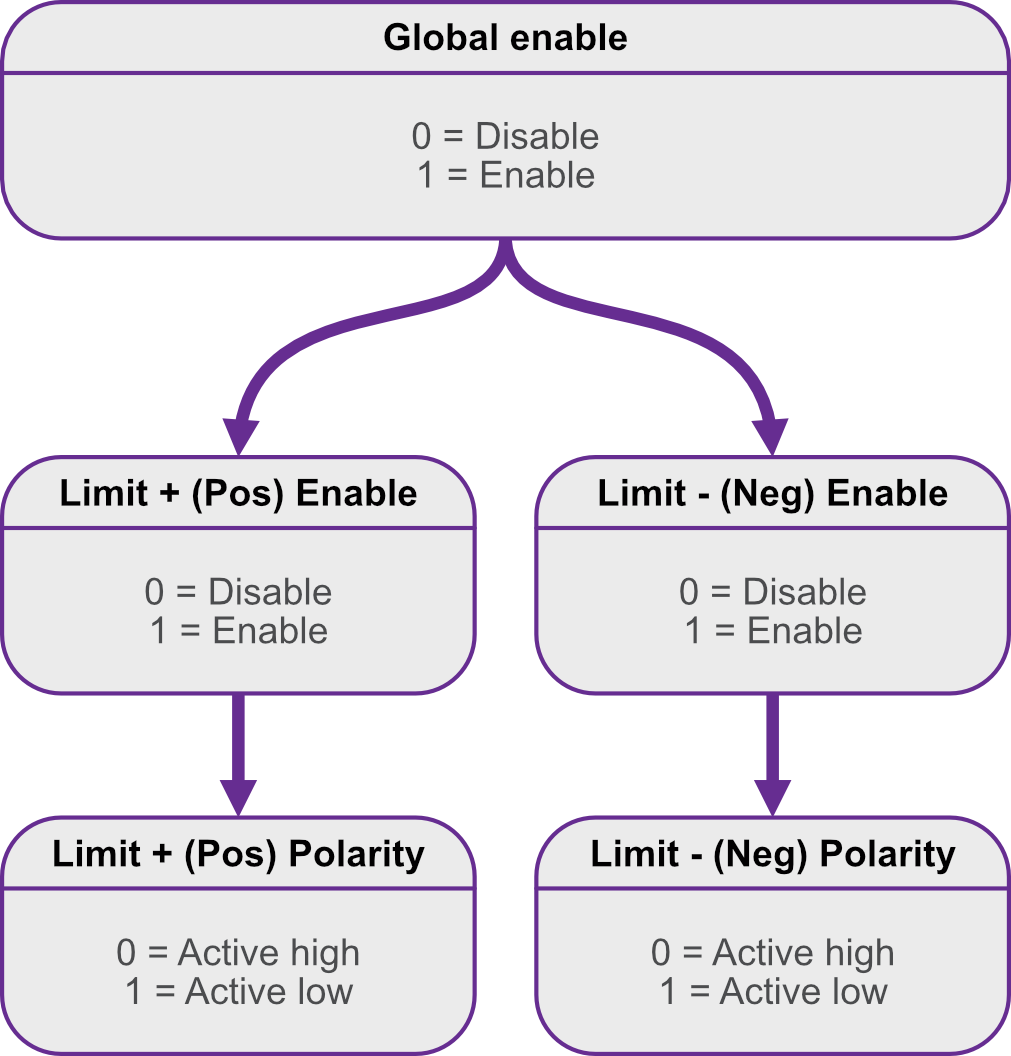
Limits
|
|

Faults
If a fault occurs, the motor is stopped and power to the motor is removed. The cause of the fault is indicated via the red front panel indicator, as shown below, and reflected in the error flags available via the remote interface.
Types of fault
|
|
Internal A hardware or software malfunction inside the SMD4. For example, user settings have becomes corrupted and failed to load properly. |
|
|
|
External enable criteria not satisfied |
|
|
|
Motor temperature Motor temperature has exceeded 190 °C or a fault has been detected with the temperature sensor. Excessive temperature can damage the insulation on the motor windings, and the SMD4 does not allow the motor to be driven. The SMD4 shuts down the motor before this can happen to prevent possible damage to the motor. Wait for the motor to cool before attempting to run the motor again.
|
|
|
|
Motor short A motor short has been detected. Motor phase to phase and phase to ground shorts can be detected by the SMD4. Inspect the motor and wiring to resolve before attempting to run the motor again. |
|
|
|
Limit hit Indicator flashes briefly once a second. A limit has been triggered and has stopped the motor. |
Clearing a fault
Faults may be cleared using the clear command [CLR],command, or by pulling the fault reset pin to the ‘GND’ pin on ‘X3 –the I/O’.O connector.
The external enable fault is non-latching when in step direction mode; once the external enable state is restored, or the external enable setting is changed to false, normal operation will resume immediately without the need to clear it as described above.