Operation
Getting started
The quickest way to get started with the SMD4 and evaluate the features described in this section (having completed wiring up according to the previous chapter) is to install the SMD4 software on your PC (see Software section), power on the SMD4 and connect it with the USB lead to the PC.
AML Device Control software allows one or more SMD4 units to be combined into a system and controlled individually or as a group. The software exposes all configuration items and makes it quick and easy to change any setting. Movements can be planned and executed. Live readouts of position, speed and status are presented.
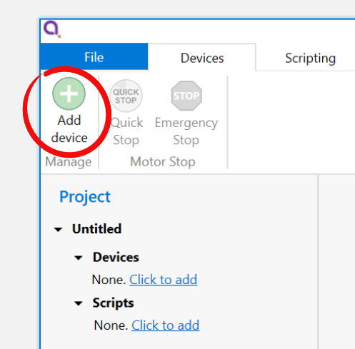
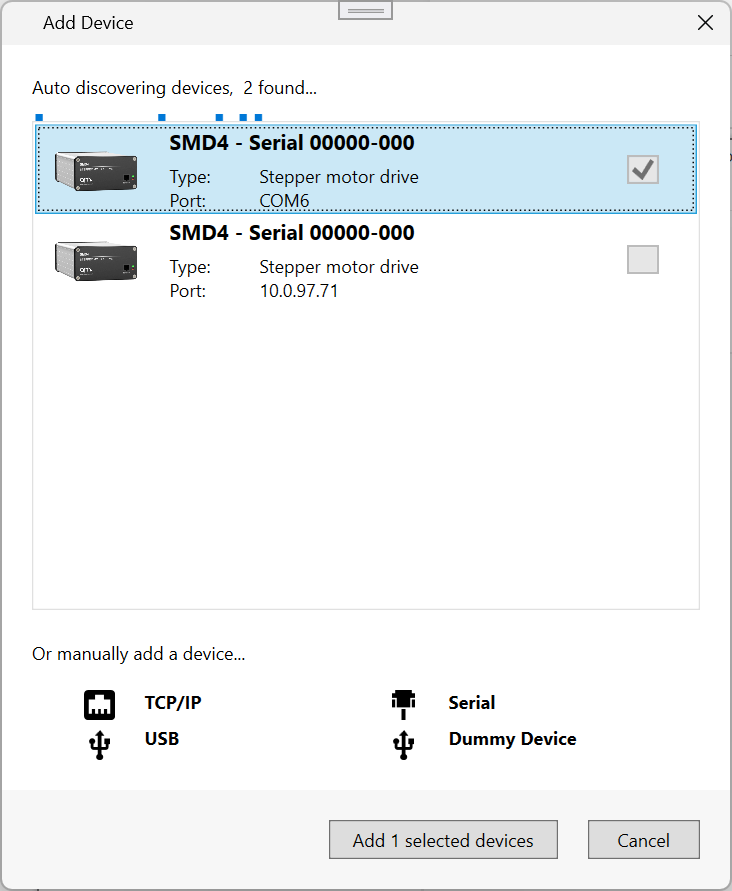
Start the software, then click "Add device" in the top left corner. A list of available devices will appear. Click your device to select it, then click the 'Add device' button.
 |
|
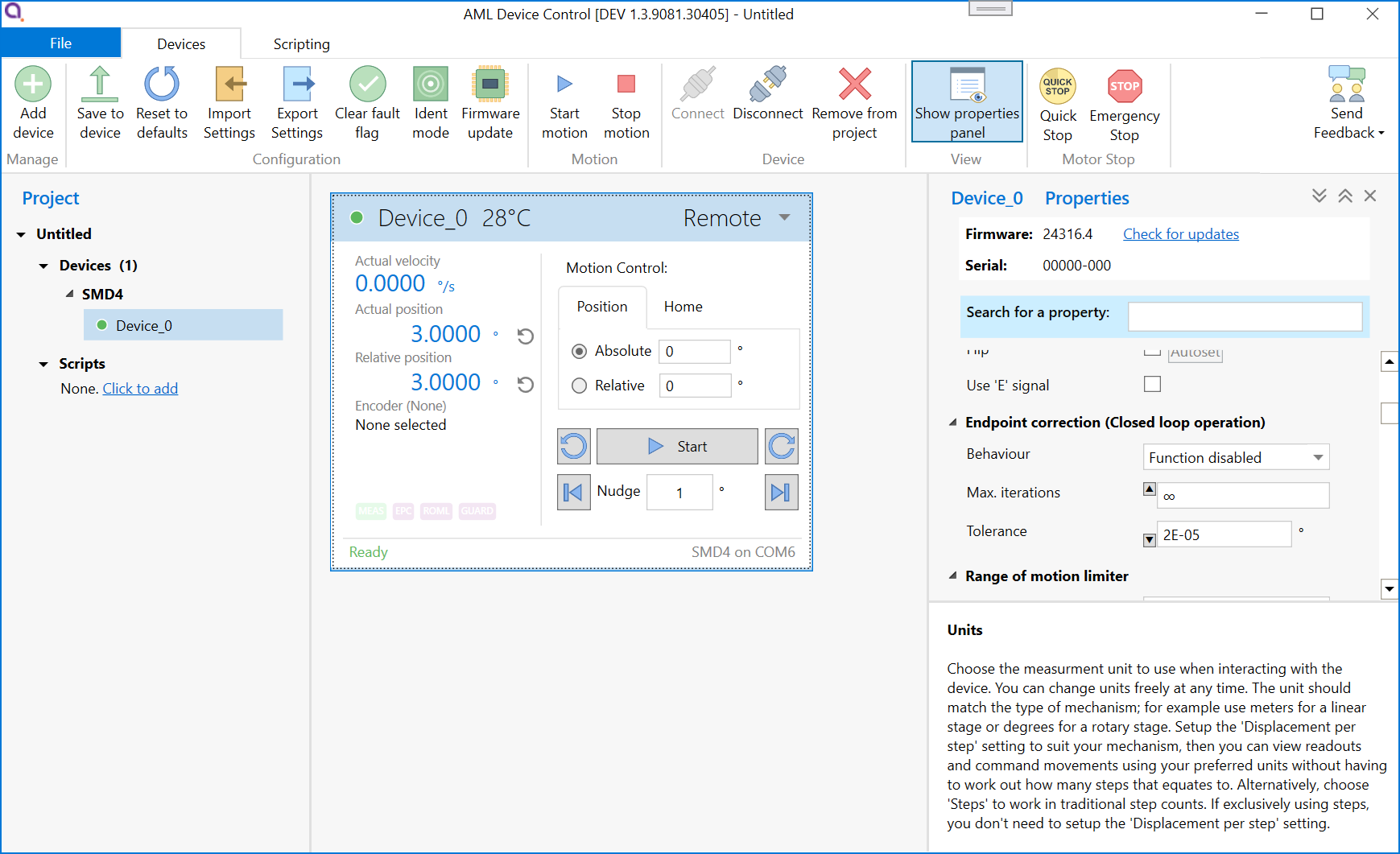
Your new device appears in the tree on the left. It can be configured using the properties panel on the right hand side, while the central window shows speed, position and temperature readouts from the device, and provides controls for planning and making movements.
 See here for more detail on the software.
Advanced users, system integrators
The remote interface uses a straightforward text based protocol, so it is easy to send commands to it using for example:
- Terminal applications
- Embedded systems
- Your own software
A C# API is available to speed up development of your own applications. Wrappers are available for other languages, including Python. The API is extensively documented and very quick to get up and running with. A quick start guide is available here.
The remote interface protocol is described in section remote interfaces.
Operating modes
The SMD4 has several operating modes:
- Normal - The default and usual operating mode
- Step and direction - Control the motor using an opto-isolated industry standard step direction interface
- Bake - Controlled heating of the motor to drive off adsorbed gasses
Configuration can be performed at any time and in any mode using one of the remote interfaces (USB, LAN or Serial).
Mode can be changed only when the motor is stopped, which can be determined from the standby flag returned in every communication, see here. Unless otherwise noted, activities described in this manual are performed in normal mode.
Persistence of settings
All changes made to the configuration via the remote interface are volatile (i.e. not retained on power cycling) unless the store command is executed before powering off. The AML Device Control software warns you of this when closing the application, but if writing a custom application to control the SMD4, your application must handle this if settings are to be persisted.
The SMD4 will always load the last stored settings on power on, or if the store command has not been previously used, defaults are loaded as per section Command Reference. If settings become corrupted, for example, the write endurance of the memory in which the settings are stored is exceeded, the SMD4 loads defaults as identified above, and a fault indication is given, see section Faults.
INFORMATION: Write endurance
The memory in which settings are stored has an endurance of about 1 Million write cycles. Only use the store command when necessary, for example, take care that your application does not perform multiple redundant store commands.
Remember to save your settings after making configuration changes!
Units
Stepper motors work in steps, and as such the core unit of the SMD4 is steps. However, this is not always meaningful in the end application, so instead you can choose a preferred unit to work in, including:
- Meters, millimeters and microns
- Inches and thou
- Degrees, radians and revolutions
To use units other than steps, the displacement per step (distance the mechanism moves, per step) must be correctly configured. The chosen unit applies globally, for example:
- Command moves such as, move relative + 10 mm
- Specify speed as 27 mm/s
- Specify acceleration as 50 mm/s^2
- Configure virtual limits at -100 mm and +100 mm
You can freely switch between like units (e.g. meters and inches), and between any unit and steps. All values are automatically converted as required. There is no loss of precision when switching between steps and other units.
When working in units other than steps, your input may not translate into an integer number of steps. The SMD4 rounds such values to the closest integer step value internally at the time of use and at the latest possible point in the processing pipeline. Your original input is always preserved.
To use units other than steps, mechanism displacement per step must be configured correctly. This is typically called resolution in the mechanism documentation and is discussed later.
Unpredictable behaviour may result if units other than steps are used and mechanism displacement per step is not configured correctly.
Mechanism setup and presets
There can be a a significant number of parameters to configure to prepare the SMD4 for use with a particular mechanism. This may include setting up encoders, limit switches, mechanism resolution and others.
The SMD4 has built in presets for most standard AML mechanisms to allow you to get up and running with a basic working configuration as quickly as possible. To use presets, locate the preset section in the properties and search for your mechanism in the list. You can enter partial or full part numbers to find your mechanism:
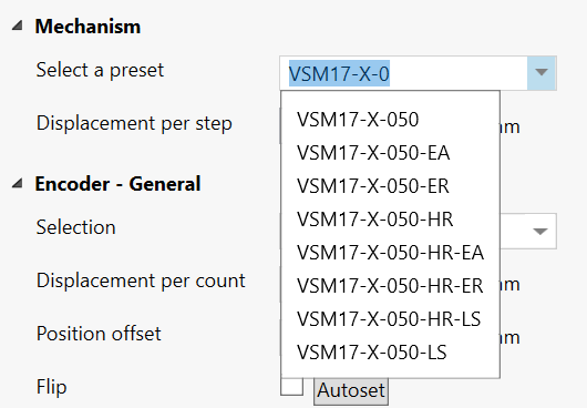
Click on the desired mechanism to select it and apply the preset configuration. Review the new configuration by inspecting the SMD4 properties. Then, experiment cautiously to confirm that the mechanism is behaving as expected. Start by making small moves at low speed until confident that the setup is correct.
Before using the preset system, review the remainder of this manual to gain a proper understanding of the drive and how it operates, then return to this section.
Points to note regarding presets:
- Several basic settings are always made (selecting an appropriate unit, displacement per step, encoder and limit switch configuration)
- Only specific settings are changed according to the preset selected, all others are left untouched. The list of changes the preset system will make varies by preset and is not published. Presets reside in the SMD4 firmware and support for new mechanisms will be added as required via firmware update.
- Various features are configured but not necessarily enabled. For example, limit switches if relevant are configured but no change is made to the global enable of limit switches, virtual limits are configured if relevant, but the virtual limit function enable state is not changed.
- If an encoder is applicable, autoflip is executed to determine correct encoder orientation. This will cause the mechanism to move a small amount, see here.
- Motor currents and profile are not changed. It is the users responsibility to configure these as required. This is discussed here.
WARNING: It is the users responsibility to verify the changes that the preset system has made before using the mechanism, and to use appropriate caution and restraint in using the mechanism until it has been established that setup is correct.
Basic motor configuration
Before running the motor, configure it first. A good order to approach this is:
- Select temperature sensor
- Configure motor currents
- Configure profile (speeds, acceleration ramps etc.)
The settings required will depend on your application and mechanism. The default settings provided are usually sufficient to get the motor spinning, but you'll need to adjust and refine these to suit. Read this section to learn more.
Steps
Stepper motors move in discrete increments, called steps. Typically there are 200 steps per revolution. When performed in quick succession, smooth continuous movement is possible. Precise movements can be made to a specific position by executing the desired number of steps. A step counter tracks the current step count, and position can be determined.
The number of steps is determined by the mechanical configuration of the motor itself. The motor drive applies varying patterns of current to the motor windings which pull the shaft to each motor step in turn and this is what results in rotation. The current applied to the motor determines how much torque is generated, and the rate at which the motor moves to each step position determines motor speed, called step frequency.
When turning the motor shaft by hand, you can feel a small 'notch' as you pass each step. This is called detent torque. The motor shaft aligns itself with the closest natural step position. Vacuum mechanisms are usually, and should be where possible, designed with balanced loads such that when the mechanism is moved to the desired place, the detent torque alone is enough to hold it in position and power can be removed from the motor.
Synchronicity
When the motor moves according to the sequence of steps it is driven with, it is said to be in sync, or maintaining synchronicity. Provided this condition is maintained, precise open loop control is possible. Open loop control is where movement is planned and made based on the assumption that the motor moved where it was commanded to.
Synchronicity can be lost under various circumstances, for example:
- Motor not powerful enough to move load
- Programmed acceleration is too fast for the motor to follow
- Inertia in the load overcomes the motor
Loss of sync may result in lost steps or a stall, in which the motor shaft stops rotating, or does so erratically.
Resonances
Stepper motors are susceptible to encountering resonances; mechanical oscillations that occur at particular operating points. Factors such as the mechanical load, speed and current all affect where and over what range resonances can occur. Resonance can result in loss of sync and or stall. Mechanisms are designed with this in mind, and aim to place any such resonances outside the applicable range of operating points. Microstepping and changes to the motor profile, discussed in the next sections can also be used to shift resonance points outside the desired area of operation.
Temperature sensor selection
AML motors can be supplied with either a K-Type thermocouple or PT100 RTD temperature sensor. Ensure the sensor is connected to the thermocouple or RTD input on the motor connector, and make the appropriate selection. The temperature sensor select command allows selection between thermocouple and RTD.
If the temperature sensor was absent, misconnected, or the wrong type of sensor was selected, the drive may be in an error state which you'll need to clear before the motor can spin. See here for information on clearing faults.
INFORMATION: The motor is disabled if the temperature sensor is misconnected, faulty or the temperature measurement exceeds 190 °C in order to protect the motor from possible damage to the insulation material.
Check that the motor temperature sensor selection matches that of your motor.
When using a thermocouple, avoid significant temperature gradients across the thermocouple leads and connector on the SMD4.
Motor currents
Different currents can be set for each phase of operation:
|
|
Applies when |
|
Acceleration |
Motor is running but not at target frequency, i.e. during acceleration and deceleration. This allows you to set a higher current during acceleration (to overcome inertia of a large load, for example) and revert to a lower current once the load is moving, thus reducing motor power dissipation and extending run time. If you do not wish to use this feature, simply set acceleration current to equal run current. |
|
Run |
Current used when motor is at target run step frequency.
Must be set equal to or smaller than acceleration current. If a change to run current makes it greater than the acceleration current, the acceleration current is automatically adjusted to be equal to run current. |
|
Hold |
Motor is stopped and is only necessary where the motor detent torque is not enough to prevent undesirable movement of the load. The cost of using hold current is increased motor temperature under vacuum. Therefore, where possible, mechanisms should be designed to be statically balanced, and the hold current should be set to 0. |
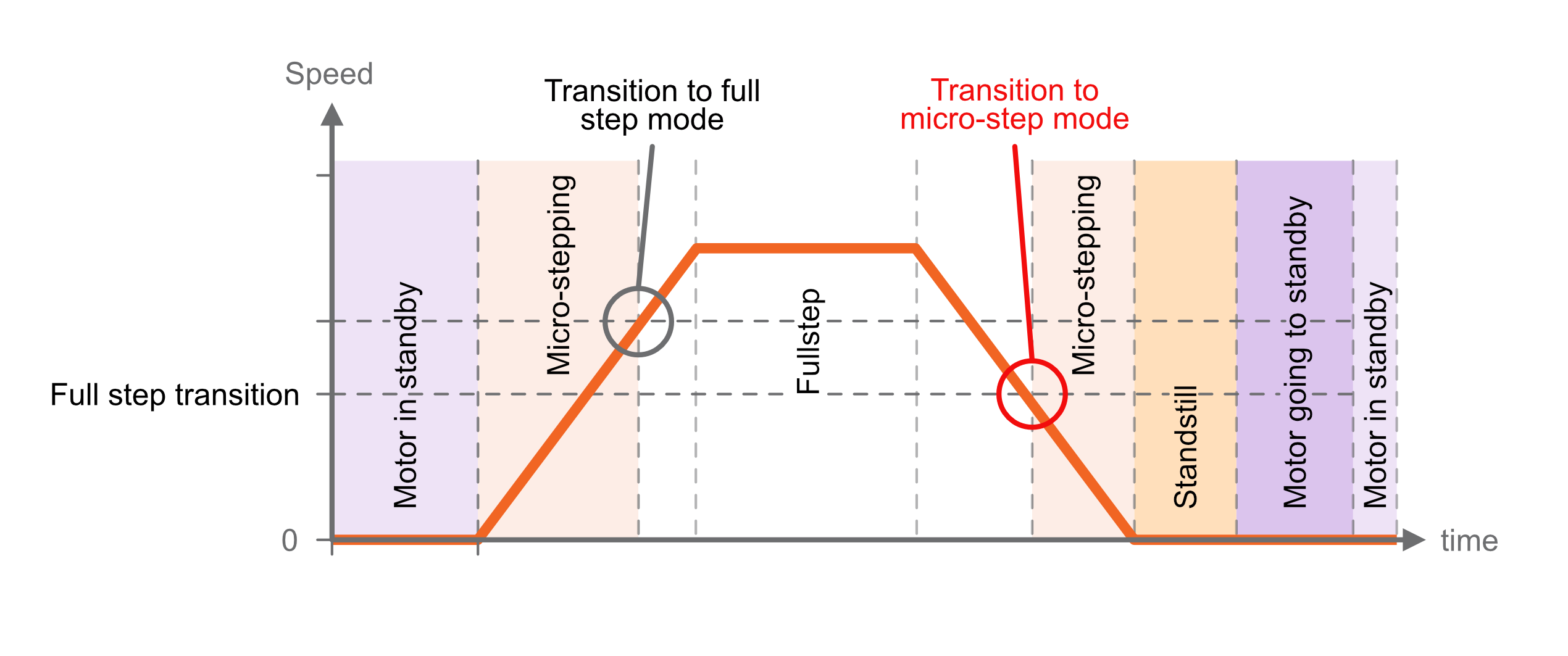
When the motor starts moving, acceleration current is applied immediately. When the motor stops after the deceleration, two additional states must be traversed before the acceleration current is reduced to hold current, first, a configurable delay during which acceleration current continues to be applied (called ‘standstill’ state), followed by a configurable delay during which acceleration current is reduced to hold current (called ‘going to standby’ state). This is shown in the graphic below:
 |
Standstill
Period after motor has stopped during which acceleration current is still applied. Adjustable between about 0 and 5.57 seconds using the ‘Power down delay’ setting [PDDEL]. Set to the minimum value suitable for your application to minimise heat generated.
Going to standby
Period during which acceleration current is gradually reduced to hold current. This smooth transition avoids a motor jerk on power down. Motor current is not continuously adjustable, instead being one of 31 discrete values from 0 to 1.044 A rms. Therefore, the current ramps down in steps. The step size may be set between 0 (instant power down) and 327 ms using the ‘Current reduction delay’ setting. Set to the minimum value suitable for your application to minimise heat generated.
Freewheel mode
Freewheel mode refers to how the motor is configured when it is at standstill and zero hold current is set. There are three choices:
-
Use freewheel for minimum holding torque, which allows the motor shaft to be moved freely.
-
Phases shorted for maximum holding torque with zero power applied to the motor (and so no heat generated in the motor).
-
Normal offers some minimal amount of holding torque as a result of the phases still being connected to the driver circuitry.
Profile
Learn how to configure microstepping and dynamic motor properties, such as speed, acceleration and deceleration. The profile settings apply for all modes except step direction mode.
The profile is configured with these general points in mind:
- Meeting the speed and torque requirements of the application
- Avoiding motor resonances that would disturb operation
- Maintaining synchronicity, avoiding step gain or loss
- Minimising temperature rise by using the lowest motor current required
The graphic below shows the basic profile:
|
|
Frequency and units
The term frequency is used throughout this manual in conjunction with motor dynamic properties, such as start frequency, step frequency and so on. This is a reference back to the way a stepper motor works; it rotates at a certain number of steps per second, or accelerates at some number of steps per second per second.
However, as discussed here recall that you can specify all these values in your chosen unit such as mm/s, or °/s^2. Where you see frequency, substitute you own unit as preferred.
Start and stop frequency
The start frequency is the initial step rate, and helps to allow the motor to overcome inertia and start moving smoothly; if start frequency were zero, the duration of the initial few steps might be long enough that the motor would overcome inertia on the first step, then effectively stop for a period of time, then have to overcome inertia once more for the second step, and so on, until the steps were frequent enough that the motor remains moving.
Stop frequency is the counterpart setting which determines the frequency for the last step.
Start frequency must be set equal to or smaller than stop frequency. This is enforced by the SMD4; if a change to the stop frequency makes it smaller than the start frequency, start frequency is automatically adjusted to be equal to stop frequency.
Start frequency and Stop frequency must be set equal to or smaller than Step frequency. The SMD4 will not force Start and Stop frequency to match Step frequency if either Start or Stop frequency are smaller than Step frequency.
Acceleration and deceleration
The SMD4 uses linear acceleration and deceleration ramps; velocity ramps up between the start frequency and the step frequency, and down linearly between the step frequency and stop frequency.
Zero wait time - Changing direction
When using higher values for the start and stop frequency, a subsequent move in the opposite direction would result in a jerk equal to start frequency + stop frequency. The motor may not be able to follow this. The zero wait time setting can be used to introduce a short delay between the two and eliminate the jerk.
Microstepping
Microstepping is applicable at low step frequencies (typically < 500 Hz) and helps reduce motor resonances resulting in smoother operation. In non-vacuum applications, it is also used to achieve increased positioning resolution, however, it requires energising both motor phases continuously even when the motor is stopped to maintain position, resulting in unacceptable levels of temperature rise in the motor in vacuum applications. Instead, mechanisms are designed to achieve the required positioning resolution with appropriate gearing.
Microstepping is not helpful at higher step rates, therefore, the SMD4 automatically switches between microstepping at low speeds and full step at high speeds. The transition point from full step to microstep is configurable, as illustrated below. Hysteresis is applied to this value resulting in the transition in the opposite direction (from microstep to full step) being at a slightly higher frequency, as illustrated above. Note that you cannot explicitly set the transition to full step point, only the transition from full step to microstep. The other transition is calculated automatically.
The resolution to use during microstepping is configurable, via the microstep resolution setting [RES]. Choices are 8, 16, 32, 64, 128 and 256. In all modes except for step/direction, the motor is only stopped in full-step positions. Microstepping is used exclusively for the purpose of smoothing the transition between steps, not to increase resolution.
The accuracy with which motor profile (acceleration, deceleration, etc.) settings may be made depends on the microstepping resolution; the maximum microstep resolution of 256 offers the greatest accuracy for these settings.
Monitoring the motor
Temperature
Motor temperature can be read back from the remote interface, see command MOTOR:T. The motor is shut down and the the drive enters a fault state if motor temperature exceeds 190 °C, or the temperature sensor is faulty, missing, or incorrectly configured.
Step/position counters
The SMD4 keeps track of position using two counters, absolute and relative position. These can be reset independently. The counters track motor step number, or index. The value may be fractional while the motor is spinning because of microstepping. When stopped the counter is always an integer value reflecting the fact that the drive only stops on full step positions.
When the counter reports a fractional value, the fractional part reflects a proportion of a full step. For example a counter value of 100.5 with microstepping resolution of 256 would mean the drive is executing microstep 128 of 256 on its way toward full step position 101. You don't need to consider microstep resolution when interpreting the counter value.
The counters behave differently with and without an encoder:
| No encoder | Encoder used |
|
Counters reflect the internal step index counters that track the electrical step number that the drive thinks the motor is on.
The step counters are used to plan movement.
Provided the motor maintains synchronicity, this will equal the motor position. |
The counters are synchronized to the encoder position whenever a positioning cycle completes.
The encoder position (not the step counters) are used to plan moves, for example relative moves are made against the encoder position, not the step counters.
At all other times, the counters reflect the open loop position.
|
When the encoder is used, it must be configured correctly for the step counters to work as expected. Improper configuration can result in erratic behavior.
If the encoder and closed loop control (see here) are not used, then motor control is open loop. Therefore, quantities such as position and velocity are determined from internal counters in the SMD4. These cannot be relied upon in certain circumstances, such as if the motor is stalled, or misses steps due to improper configuration.
Moving the motor
There are fundamentally two types of move that can be made. Regardless of how the move is initiated (joystick, remote interface etc.) it resolves to one of these two types of move:
| Position | Spin |
|
Move to an absolute position or by a relative distance, for example:
|
Move indefinitely in a given direction:
|
Therefore, the following basic moves can be made:
- Move absolute
- Move relative
- Spin clockwise
- Spin counterclockwise
The drive wraps these basic functions to perform more complex functions such as closed loop positioning using an encoder, see here.
Specifying direction
Direction is specified as positive, which results in the position counter incrementing, or negative which results in the position counter decrementing.
When wired per instructions in this user manual, AML motors spin as follows, when viewed from the rear of the motor:
| Direction | Shaft spins... | |
| Positive | Clockwise | 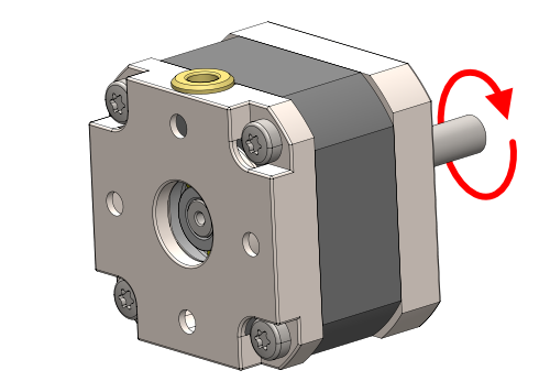 |
| Negative | Counter-clockwise |  |
The direction a mechanism moves in is not usually specified and depends on:
- The particular mechanism and its gearing
- Your perspective given the mounting orientation on the mechanism
You should therefore evaluate this in your application, and follow these instructions if required to flip motor direction so that positive and negative directions correspond as required.
Stopping
Moves can be terminated at any time by stopping. There are several ways to stop:
| Stop | Quick stop | Emergency stop |
| Motor will decelerate to a stop using the current profile. |
The deceleration profile is truncated as required to cause the motor to come to a full stop within 1 second.
The original profile is unmodified.
If the existing profile would bring the motor to a stop in under 1 second then that profile is used. |
Immediate full stop, and cut all electrical current to the motor. The motor is inert and unpowered.
The internal position counters become invalid because synchronicity is lost.
|
The stop and emergency stop commands can originate from within the SMD4 without external input:
- Emergency stop is raised when the SMD4 encounters a fault condition, see here.
- During processes such as homing and closed loop control
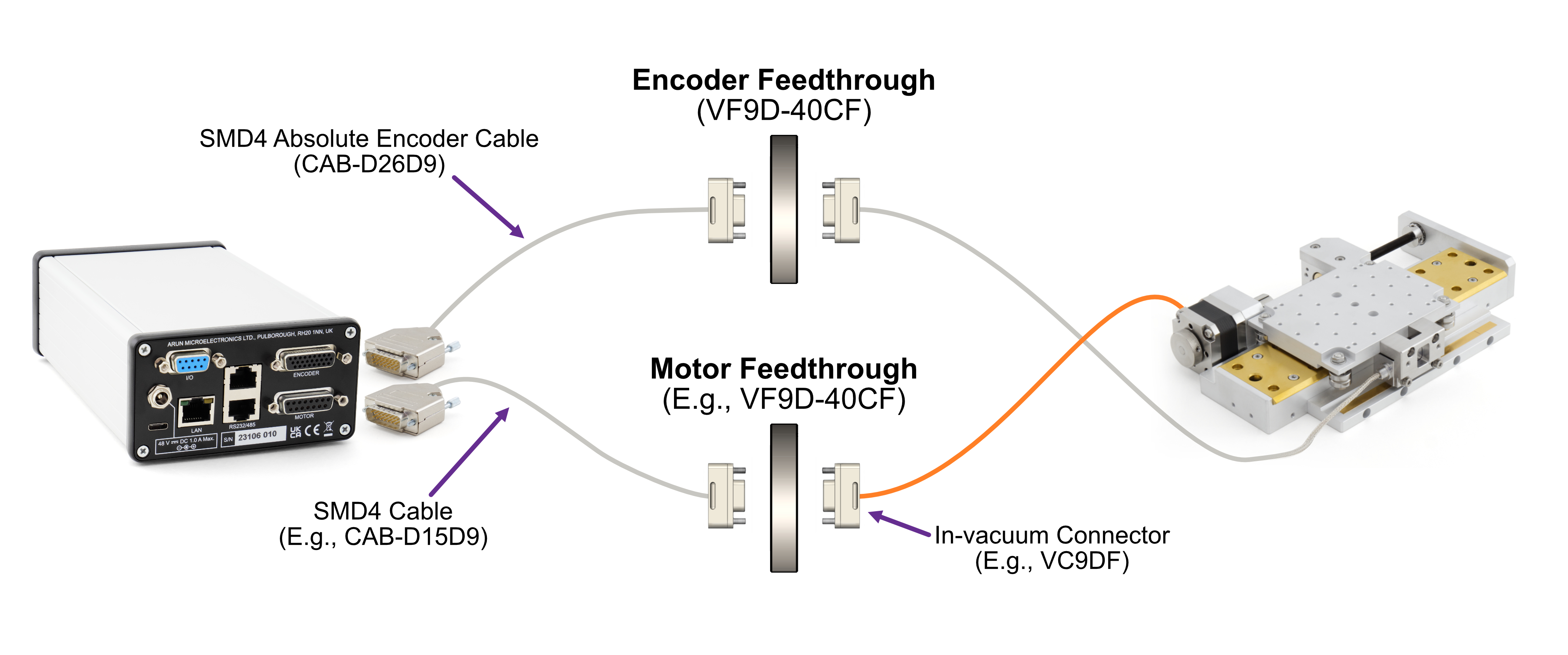
Encoders
Encoders allow the real mechanism position to be read, independent of position as determined by the step count. Encoders make closed loop control, in which the actual position and target position are continuously monitored and the corrections automatically made to minimise error, possible.
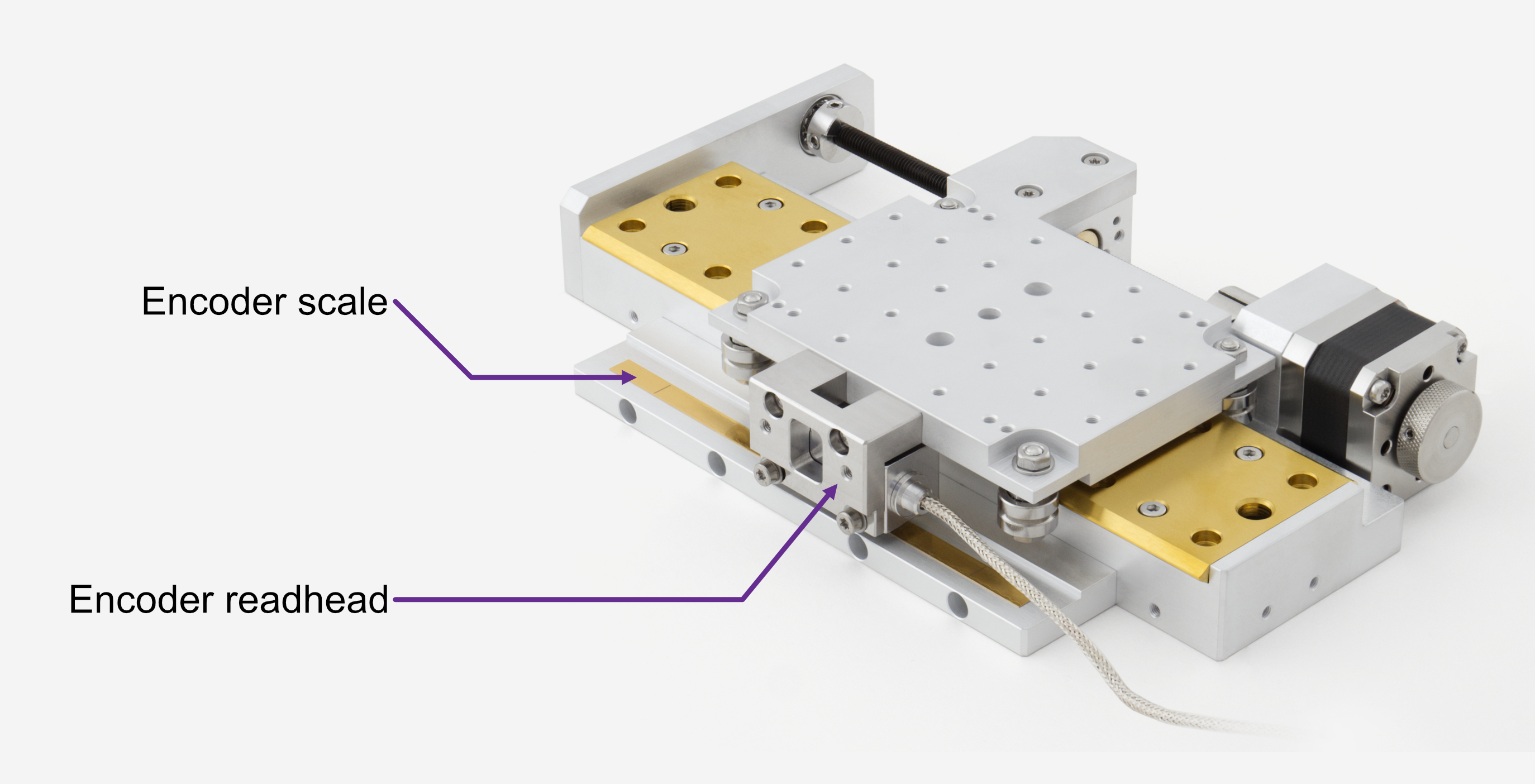
Supported encoders fall into two broad categories, incremental and absolute. Both are available in linear, angular and partial arc forms to suit different mechanisms. Both involve a scale and readhead.
The scale is typically a microscopically patterned thin metal strip affixed to the bed of the mechanism. The readhead is a small optical module attached to the carriage of the mechanism and reads the scale as it passes underneath. The scale is always sized such that the readhead can see it at any point within the physical travel of the mechanism.
Supported types
The SMD4 works with most incremental and absolute encoders meeting the requirements given here. Support for other encoder types may be added via firmware update, for example supporting word lengths other than 26 bits for absolute BiSS encoders; please contact us for details.
Incremental encoders overview
Incremental scales feature a repeating pattern. The readhead outputs quadrature A and B sine waves that encode the readhead position and direction as it passes over marks on the scale. These are passed to an interface external to the SMD4 which interpolates and outputs digital A and B quadrature signals. These signals drive a counter in the SMD4 encoder interface module which represents position.
The position is volatile and stored only in the counter on the SMD4, unlike in the case of the absolute encoder. The incremental encoder only provides pulses which are used to increment or decrement a counter according to direction of travel. If power is lost, the count is lost. If the mechanism is moved while powered off, there is no way to detect this.
An external interface sits between the encoder readhead and the SMD4. This is provided with the encoder supplied with the mechanism. These are specified with an interpolation factor, for example 20x. Incremental scales are specified with a pitch, for example 20 um. The interface interpolates this to increase the resolution, for example a 20x interface and 20 um pitch scale = 20 um / 20 = 1 um resolution.
Incremental encoders have several additional functions:
- P and Q limits - For linear scales, small magnets can be placed to mark limit points. The magnets are detected by the readhead and trigger a limit signal. Read the instructions for your mechanism to learn more.
- Error - An error signal is activated if for example, the readhead cannot read the scale properly.
- Z reference - Precision reference marks are placed on the scale. For angular scales, there is one mark, for linear scales there are multiple marks placed at fixed intervals, and the desired mark is selected by a small magnet placed next to it. When the readhead approaches the mark from either side, the Z signal is triggered. This can be used for establishing a datum position. Read the instructions for your mechanism to learn more.
The electrical interface requires these pins:
| Name | Function |
| A+ | Quadrature 'A' signal |
| A- | |
| B+ | Quadrature 'B' signal |
| B- | |
| Z+ | Quadrature 'Z' signal |
| Z- | |
| P | Limits and error signals |
| Q | |
| E | |
| 0 V | Power |
| 5 V | |
| ... For a total pin count of 11 pins | |
This generally requires a 15 way D-Sub feedthrough or similar. The pin count can be reduced to an absolute minimum of 6 pins, if the P, Q, E and Z signals are not required. The E signal is optional on the SMD4, and can be disabled/ignored if not required although this is not recommended.
Absolute encoders overview
Communication with the readhead is via a digital coms interface, and data are sent to the SMD4 from the readhead in packets verified by a CRC. The readhead connects directly to the SMD4 encoder interface module.
Absolute scales are patterned in such a way that the readhead can determine without any prior reference exactly where it is positioned, much like looking at a ruler. The absolute encoder therefore knows its absolute position at any time. The electronics can be powered off, the mechanism moved, and powered back on, and the readhead can still determine its absolute position.
Absolute encoders are specified by their resolution, for example 50 nm/count. The readhead outputs an absolute count value representing the position on the scale, from zero at one end, increasing toward the other end. The maximum count you will see for a given mechanism depends on the encoder resolution and scale length.
The scale cannot be positioned with micron level accuracy, so the zero count will not align with either end of the mechanism and there will always be a small offset. This also accounts for thermal effects, allowing extra scale at the ends of travel. For example, on a 50 mm linear stage, positioned at the negative extreme of travel might read a count of 46789, corresponding to a position of 50 nm x 46789 or 2.34 mm. Use the zeroing features of the SMD4 to set your own zero point.
Linear and partial arc scales start at zero and the maximum count depends on the length. For a 50 nm resolution system on a 50 mm scale the maximum count is at least 50e-3/50e-9 = 1e6. We can also infer from this that the maximum length scale for this 50 nm system with 26 bit BiSS is 50 nm * 2^26 or about 3.3 m.
Angular (circular) scales count from zero to the maximum value then back to zero. For a 26 bit system, this means the count goes from 0 to 2^26 - 1 the next count on from 2^26 -1 is 0.
The scale is generally patterned at a much larger pitch than the published resolution, because the readhead uses interpolation techniques to obtain the published resolution.
The electrical interface requires these pins:
| Name | Function |
| MA+ | Clock |
| MA- | |
| SLO+ | Data |
| SLO- | |
| 0 V | Power |
| 5 V | |
| ... For a total pin count of 6 pins | |
The much reduced pin count and simplicity of absolute encoders versus incremental makes them ideal for vacuum use. The overall system requires fewer components, less space, fewer feedthrough pins in addition to the advantages of having an absolute readout.
Handling of encoders
The SMD4 treats all encoder input as absolute. When an encoder is online and selected, the encoder is used to plan all movements. Moves you command are with respect to the encoder position, not the step counters. If any error occurs with the encoder in use, then a fault is triggered and the motor is disabled.
When an encoder is enabled, you can read speed and position data directly from it, as well as use it for functions such as closed loop control and virtual limits. These additional functions are discussed later.
It is essential that the encoder is correctly setup before use, otherwise unpredictable behaviour will result.
Special considerations for incremental encoders
Incremental encoders can in theory be treated as absolute provided that:
- An initial reference is established at first power on
- The save features of the SMD4 are utilised to save positions before power off
- The mechanism is never disturbed when the SMD4 is off
- Encoder operation is never interrupted
In practice, even if close attention is paid to these points, effects such as thermal expansion and contraction cannot be accounted for when powered off. As such, incremental encoders are usually used with a reference switch or other means to establish a fixed reference at power up if absolute position is important.
Special considerations for absolute angular encoders
To allow for more than one rotation to be tracked (recall that absolute angular encoder rings count from 0 to a maximum value, with the next count being 0) the SMD4 treats the absolute encoder in a pseudo incremental manner. This involves two counters, the 26 bit unsigned integer count from the readhead (readhead count), and a 64 bit signed counter maintained on the SMD4 (SMD4 count):
- At startup, SMD4 count is set equal to readhead count
- As the SMD4 runs, the readhead count is sampled rapidly, and the difference between this and the last readhead count is added to the SMD4 count
The properties of wraparound integer arithmetic ensure the proper behavior when the readhead counter crosses over the maximum count to zero, or vice versa, boundary.
This allows (at least during the power on time of the SMD4) multiple rotations to be tracked, and the availability of all encoder functions. For example, closed loop control could be used to home to a location of 100.5 revolutions, or virtual limits used to prevent a rotary mechanism from rotating too many times and tangling its leadout wires.
Setting up an encoder
Having connected the encoder and powered on follow these steps to manually configure an encoder. Values for settings required here can be found in the documentation supplied with your mechanism. This section assumes the drive is otherwise configured and working.
Alternatively, use the SMD4s built in presets functionality to automatically configure these settings to suit your mechanism, see mechanism setup and presets.
| Step | Details | |
| 1 |
Check encoder indicator lights |
Check indicator light on encoder is on. There might be more than one light.
For Renishaw encoders shipped with AML mechanisms, provided the light or lights are on and any color other than red, you may proceed. A red light usually indicates a fault which should be fixed before proceeding. Refer to the documentation provided with the mechanism for more details. |
| 2 | Select the encoder | Set encoder selection to incremental or absolute as required, and decide if the error signal should be used (incremental only) |
| 3 | Set units |
Configure the units (degrees, meters etc. to suit your mechanism if not already done so).
It may be convenient to set a unit here that matches that in the mechanism documentation. |
| 4 | Set mechanism displacement per step | This is the distance moved by the mechanism per step, usually referred to as the resolution in user documentation. |
| 5 | Check mechanism direction | Make one or more small moves and verify that directions are as you expect. If not, then see here to reverse motor direction. |
| 6 | Set displacement per count | This is the distance moved per encoder count. For example, for linear absolute encoders this might be 50 nm. If units are set to meters, you can simply enter 50e-9. |
| 7 |
Determine flip |
The direction of the encoder scale must match that of the motor, i.e. when the motor moves in a positive, incrementing direction, the encoder must also.
A flip option allows the encoder to be virtually flipped to match the motor direction. An autoset feature is available; use this to automatically set flip as required. The motor will move a small distance to do this, and will return to its original position when complete. |
| 8 | Zero the encoder | Position the mechanism at the desired zero point, either using the motor or by hand, then reset the absolute and relative counts as required. Finally use the save/store to device function to save your changes. |
Closed loop control (Endpoint correction, EPC)
This feature uses an encoder to automatically minimise positioning errors. The SMD4 works continuously, monitoring position and adjusting the mechanism to your target position.
Introduction to closed loop control
Without an encoder, the SMD4 can only function in open loop mode. In open loop control, the SMD4 generates the required number of steps to perform the requested move and assumes that the motor moved the corresponding amount. There is no feedback to the SMD4 that the motor moved as expected. This approach works well with stepper motors because provided they maintain synchronicity fast accurate movements can be made without the need for feedback. This reduces cost, complexity and requires fewer components in vacuum.
In closed loop control, the SMD4 monitors the actual position of the mechanism via the encoder, and corrects for deviations when they occur.
How it works
Closed loop control on the SMD4 works using a method called Endpoint Correction, or EPC. In traditional closed loop control, actual and demand positions are continuously monitored, and a control algorithm adjusts motor movement to compensate out any errors. Proportional, integral and derivate gains are configured to obtain the desired system characteristics in terms of responsiveness, overshoot, undershoot and residual error.
EPC uses a different approach. A simple explanation, omitting some detail, is that every movement is initially made open loop. When the open loop move has completed, the actual and target positions are compared and position error determined. If the error falls below a user specified threshold, nothing more is done and the move is complete. If the error exceeds the threshold, a second move is made, again open loop, to try and eliminate the error. This process is iterative and continues either until the error has reduced below the threshold, or a specified maximum number of iterations of adjustment have occurred.
Once a move has completed, EPC continuously monitors position error and makes further adjustments if the error exceeds the threshold. In this way, EPC responds to events such as thermal effects or disturbance of the mechanism even when stopped.
Baseline error after each cycle of EPC is tracked, and cumulative error is considered for the next cycle.
EPC is optimised for vacuum use and allows closed loop control while minimizing temperature rise with little effort required by the user to configure it.
Configuration
Behavior
Defines what the feature should do:
- None – Feature is disabled/inactive
- Warn – Feature is enabled, and can raise a warning on alarm
- Error – Feature is enabled, and can raise an error on alarm
An alarm is the feature raising a notification. A notification is not necessarily an error, and the meaning is different for each feature. You can choose to route the alarm to a warning, or an error as described above by the behavior option.
Warnings are recorded but cleared automatically on the next successful move.
Errors are recorded and put the drive into a global fault state stopping the motor. An error must be cleared by the user to restore normal operation.
Maximum iterations
Maximum number of moves that EPC will make to correct position after the open loop positioning phase is completed. This can be set to a finite value or infinity, in which case the number of allowed moves is unlimited.
The moves count is zeroed at the start of each commanded move, and when a move successfully completes. If the mechanism is disturbed when stopped, a new cycle of corrections begins with the move count starting at zero once more.
Tolerance
When error reduces below this value, the move cycle is considered complete. The minimum value possible is half the mechanical resolution of the mechanism. Minimising tolerances results in more accurate positioning, at the expense of more adjustment and greater sensitivity to responding to disturbances. Larger tolerances result in less accurate positioning.
Alarm behaviour
An alarm is raised when:
- Maximum number of positioning iterations exceeded for this move
- The specified tolerance is impossible to meet given the mechanism resolution
Range of motion limiter (Virtual limits, ROML)
Virtual limits are limits defined based on position.
When configured, range of motion is limited to the range specified. Demand position is adjusted if required to prevent the motor moving outside the specified range. For example, if a continuous rotation is demanded, and a virtual limit exists in that direction, your command is converted into a move to the virtual limit position. The motor will come to a stop at the limit using your specified profile.
If an encoder is present and the mechanism is forced outside the range of the virtual limit by an external means (for example, the mechanism is forced by hand) this is reported to the user.
This feature will work without an encoder, in which case the position is open loop and taken from the internal step counters.
Configuration
Behavior
As here.
Value one and two
These define the two virtual limits. There is no requirement for them to be in any particular order, for example value one might be 4 mm and value two -4 mm.
Alarm behaviour
Alarm is raised when:
- Movement outside the virtual limits is commanded (even though ROML will adjust the commanded move to prevent that happening)
- The mechanism is externally forced outside the limit range. This is only applicable to the encoder.
Guard
This feature is like ROML, except that it does not adjust your input to prevent movement outside the specified range, and only warns or generates an error after movement outside the specified range has occurred.
This feature will work without an encoder, in which case the position is open loop and taken from the internal step counters.
Configuration
Behaviour
As here.
Value one and two
These define the two virtual limits. There is no requirement for them to be in any particular order, for example value one might be 4 mm and value two -4 mm.
Alarm behaviour
Alarm is raised when:
- Movement outside the virtual limits is commanded
- The mechanism is externally forced outside the limit range. This is only applicable to the encoder.
Using the joystick
|
The joystick is a two button controller on coiled lead that plugs into the front panel.
Use the right button for movement in the positive direction, and the left for movement in the negative direction. All moves occur according to the current profile in the drive.
It is available any time it is plugged in and enabled (see operating modes), and has several modes of operation. It is a quick and easy way to simply move the mechanism without touching it. This can be useful during commissioning, or even as the primary means to control you mechanism. |
 |
| Single | Brief press to move one step, hold to move continuously, release button to stop |
| Continuous | Brief press to start moving continuously, subsequent press to stop |
| Nudge | Brief press to trigger a user defined relative move, called a nudge. Subsequent press stops |
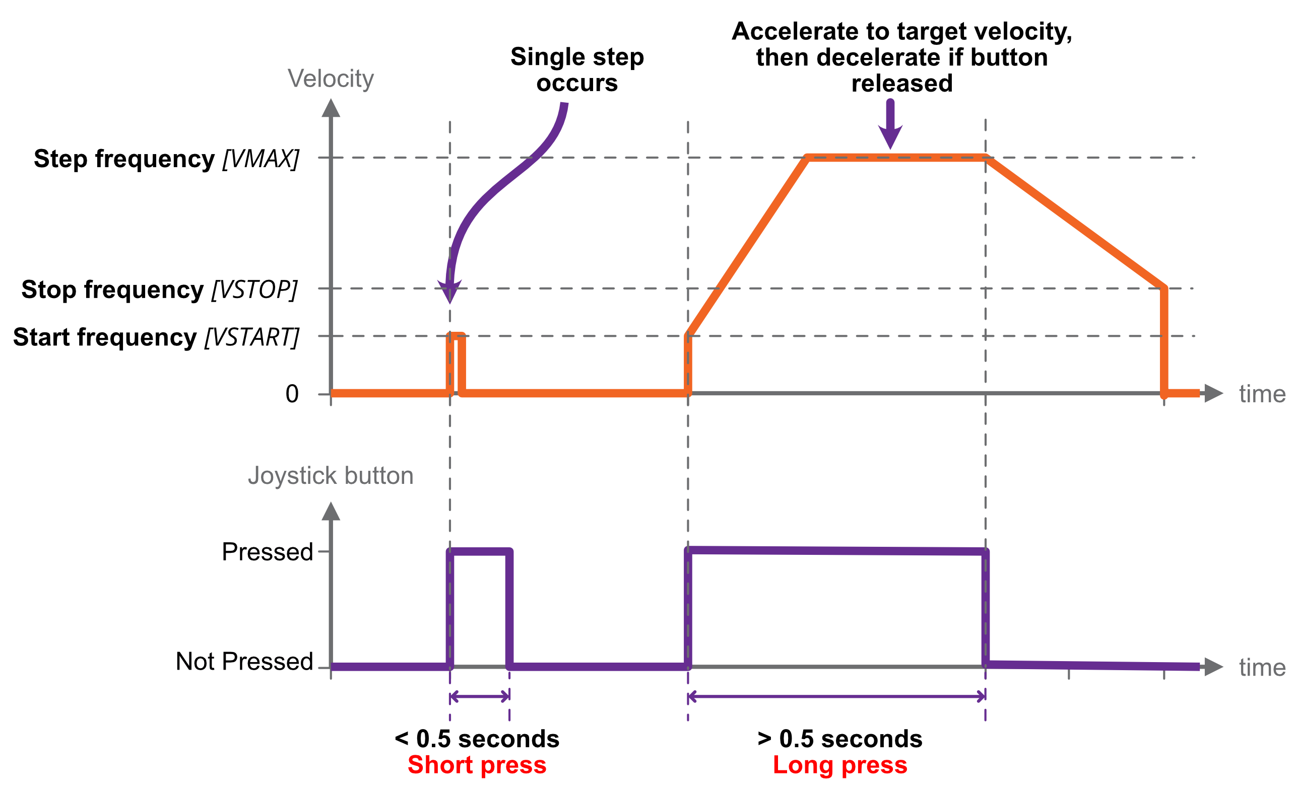
Single
|
|
A short button press (< 0.5 s) causes a single step in the commanded direction. This is useful for precise positioning.
A long press (> 0.5 s) triggers acceleration toward the target frequency, while the button continues to be pressed.
Releasing the button causes the motor to decelerate toward a stop.
If the button is pressed while the motor is still decelerating, the motor once more accelerates toward target frequency for as long as the button is held.
|
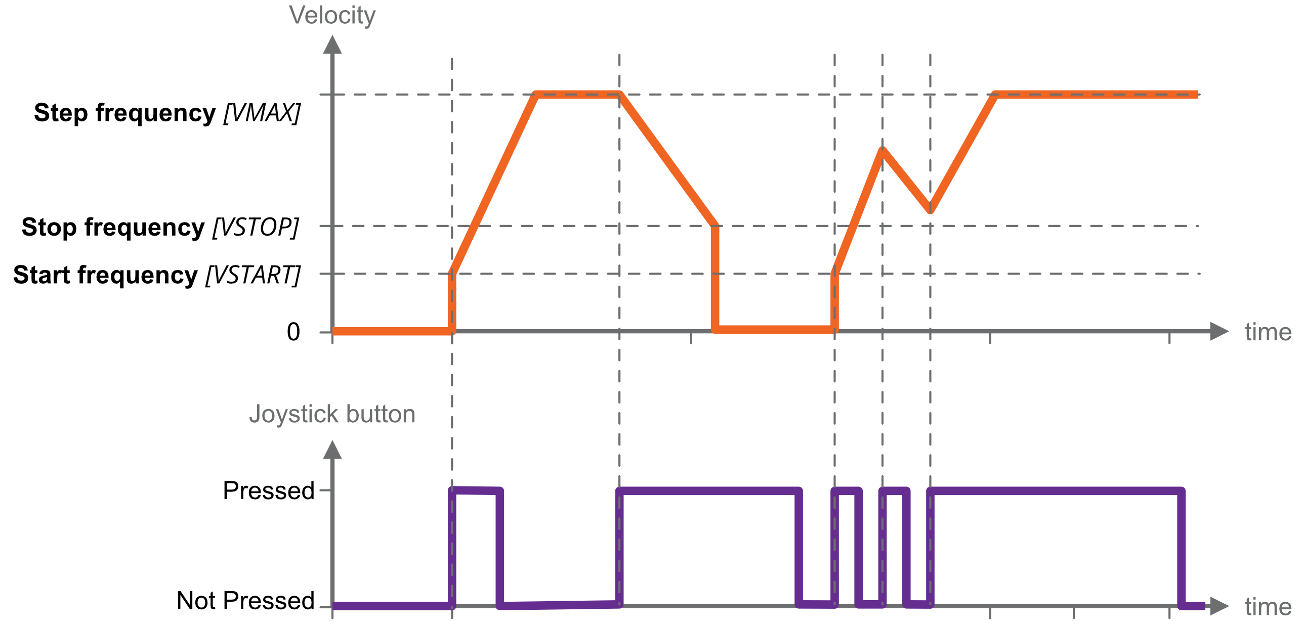
Continuous
|
|
Motor accelerates toward target frequency on joystick key down. Continuing to hold the key down has no further effect.
On releasing and pressing the same key again, the motor decelerates toward a stop.
On pressing the alternate direction key, motor first decelerates to a stop before accelerating toward target frequency in the other direction.
If the motor has not yet come to a stop, and the same key is pressed again, the motor will once more accelerate towards target frequency, as illustrated left. |
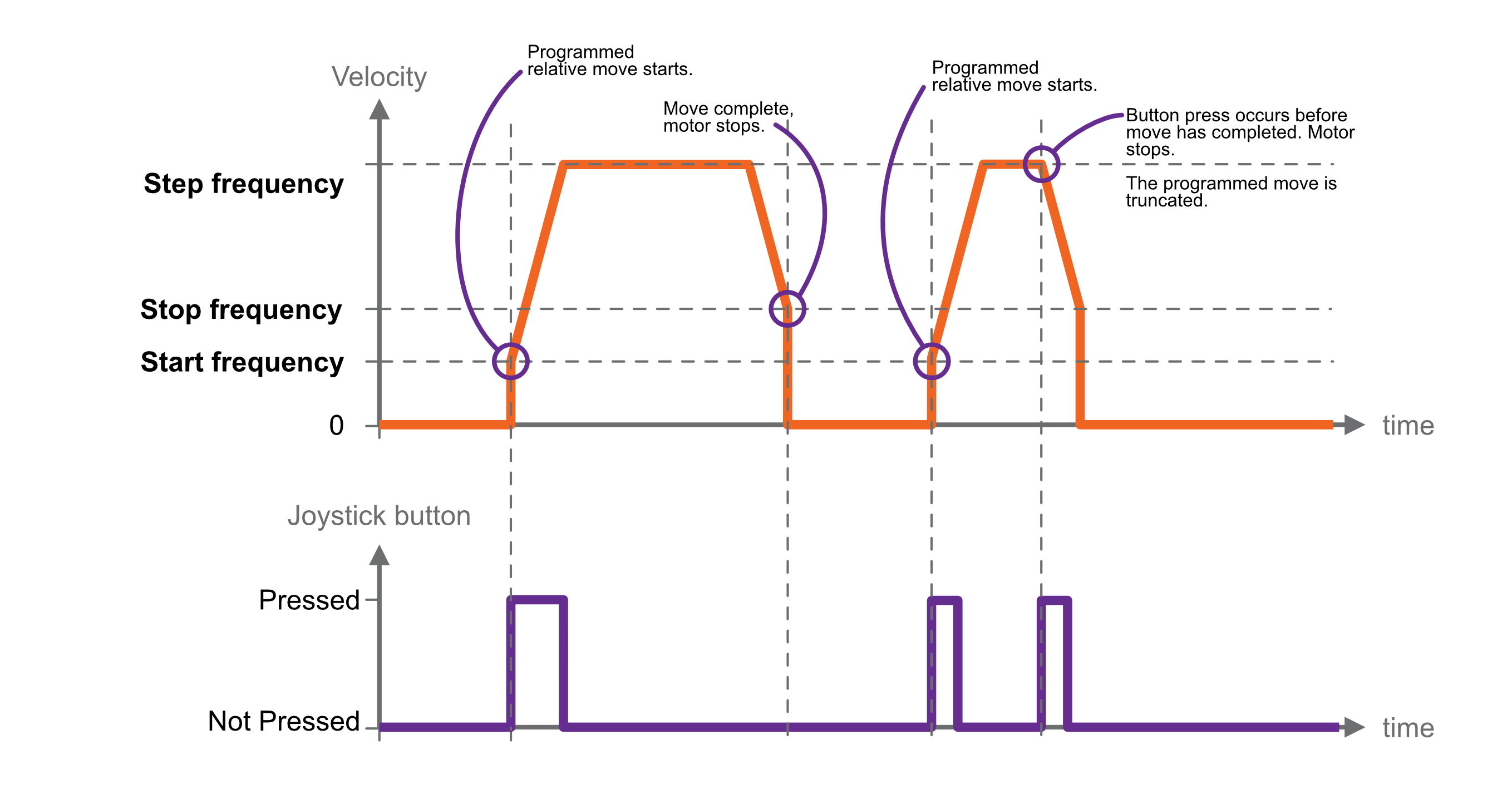
Nudge/Relative move
|
|
Trigger a pre-defined relative move with the joystick.
You specify the distance, or nudge value, and trigger the move to start in the desired direction according to which joystick button is pressed.
On pressing a joystick button, a relative move of the specified distance and direction is made.
If any button is pressed while the move is in progress, the motor decelerates to a stop and the commanded move is not completed.
|
|
The nudge value is signed, and the relative move performed is the product of the button and nudge value. The negative button multiplies the nudge value by -1, and the positive button +1. For example, if the nudge value is -100, and the negative joystick button is pressed, then the relative move made will be -100 * -1 = 100. |
|
Homing to limit switches
Some mechanisms include one or more limit switches, positioned typically at the limits of travel or other reference position.
Homing is an automated procedure where the motor is driven to a chosen limit switch in a precise and repeatable manner. Most users then reset the position counters, and use that position as a reference going forward.
Homing only works with physical limit switches.
Homing cycle
You can choose to home in the positive or negative direction.
The motor first moves toward the limit switch using the existing movement profile. On the limit switch being triggered, the step frequency is halved, and the motor reversed until the limit switch is not triggered. Finally, the motor moves toward the limit switch at a step frequency of 30 Hz until the limit switch is triggered.
INFORMATION:
Limit switches are not latching, i.e. as soon as a limit input becomes not triggered, for example if the mechanism is able to first actuate a limit switch and then continue moving past it until the limit switch is no longer actuated, then the SMD4 will be unaware of this and will continue to drive the motor if commanded.
Limits switches and cams are normally arranged such that the limit switch is triggered from the desired point up to and including the point at which the mechanical limit of the mechanism is encountered.
Step and direction interface
Motor movement is controlled by externally supplied step and direction signals. There are two sub modes, normal and triggered.
Set the mode to step and direction to use this function. Once in step direction mode, motor movement can only be controlled via the step direction interface, and not via other means such as the joystick or remote interface.
Normal mode
The SMD4 can be configured to step on the rising or rising and falling edges, which halves the step clock rate required.
The external enable fault is non-latching when in step direction mode; once the external enable state is restored, or the external enable setting is changed to false, normal operation will resume immediately without the need to clear it.
|
Step input |
|
Direction input |
|||
|
Both |
Rising only |
|
|
Meaning |
|
|
Rising |
Step |
Step |
|
Low |
Positive |
|
Falling |
Step |
|
|
High |
Negative |
Steps are generated according to the current resolution. For example, with the edge setting on rising only, and microstep resolution set to 128, each rising edge on the step input will generate a single 1/128th step.
A step interpolation option is available; when enabled, the step input behaves as it would with the current resolution, except that each step input is interpolated to 256 microsteps. This is done by evaluating the rate at which steps arrive and timing 256 microsteps within the step-to-step period. This gives all the benefits of microstepping at high resolution while minimising the input clock rate.
The relationship between step input, resolution and actual step frequency is given below:
Motor Step frequency [Hz] = (Step input [Hz] / Resolution)
INFORMATION: Stopping on fractional steps
There is no mechanism to prevent the motor from stopping on fractional steps as there is in all other modes.
Stopping on fractional steps will result in the motor temperature rising much faster than it otherwise would and is generally not suitable for vacuum applications. Therefore, configure the external step generator to meet this criteria.
INFORMATION: Preparation before switching out of Step/Direction mode
When changing to another mode from Step/Direction mode, ensure that any movement being commanded via Step/Direction interface has completed, and that the motor is at a full step position before switching.
Triggered mode
This mode works the same as joystick continuous mode, except that the positive and negative inputs that would normally be supplied via the joystick input are instead generated from the step and direction inputs:
|
Step input |
|
Direction input |
||
|
Meaning |
|
|
Meaning |
|
|
Rising |
Triggers start / stop |
|
Low |
Positive |
|
Falling |
No action |
|
High |
Negative |
In the case of Step/Direction mode, it is the responsibility of the external controller to perform any final activities, such as coming to a stop, before changing the mode.
Bake
Heats the motor by energising both phases and holding the motor stationary, regulating the current to achieve a set point temperature. Used to drive off adsorbed moisture in the motor.
Set the mode to bake to use this function.
Before engaging bake mode, set the target bake temperature. When in bake mode, the green status indicator will flash briefly at intervals as a reminder that this mode is active.
Enable input
An enable input is present as part of the SDE interface, but the enable signal may be used in any mode. The motor is enabled when high and disabled (all motor movement inhibited) when low.
The enable input is ‘gated’ by an external enable setting; when enabled, the behaviour described above applies. When disabled, the enable input is treated as if it was true, regardless of the actual state. This allows the user to decide whether the enable input is used or not.
When the enable input is not used, then the SMD4 is responsible for enabling the motor as required, consistent with any other requirement described in this document.
|
Enable input |
||
|
|
Setting enabled |
Setting disabled |
|
Low |
Motor disabled |
Motor enabled |
|
High |
Motor enabled |
Motor enabled |
Limits
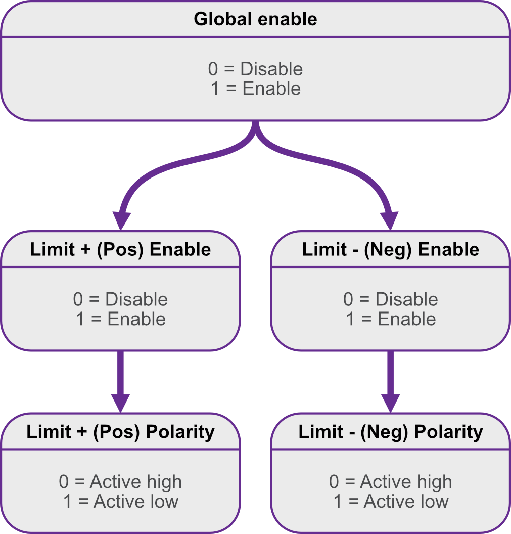
|
|

Faults
If a fault occurs, the motor is stopped and power to the motor is removed. The cause of the fault is indicated via the red front panel indicator, as shown below, and reflected in the error flags available via the remote interface.
Types of fault
|
|
Internal A hardware or software malfunction inside the SMD4. For example, user settings have become corrupted and failed to load properly. |
|
|
|
External enable criteria not satisfied |
|
|
|
Motor temperature Motor temperature has exceeded 190 °C or a fault has been detected with the temperature sensor. Excessive temperature can damage the insulation on the motor windings, and the SMD4 does not allow the motor to be driven. The SMD4 shuts down the motor before this can happen to prevent possible damage to the motor. Wait for the motor to cool before attempting to run the motor again.
|
|
|
|
Motor short A motor short has been detected. Motor phase-to-phase and phase-to-ground shorts can be detected by the SMD4. Inspect the motor and wiring to resolve before attempting to run the motor again. |
|
|
|
Limit hit Indicator flashes briefly once a second. A limit has been triggered and has stopped the motor. |
Clearing a fault
Faults may be cleared using the clear command, or by pulling the fault reset pin to the ‘GND’ pin the I/O connector.
The external enable fault is non-latching when in step direction mode; once the external enable state is restored, or the external enable setting is changed to false, normal operation will resume immediately without the need to clear it as described above.