Guidance on use of VCSMs
It is assumed that the reader is familiar with the production and handling of UHV components. The successful application of vacuum stepper motors requires an appreciation of their thermal as well as their mechanical properties. Compared to motors operated in air, the available cooling means for motors in vacuum are much less effective.
Apart from extending the run time, operation at a low temperature improves the outgassing performance of motors. Therefore, minimum running times and motor currents should always be pursued. Selection of the largest motor possible for the application will result in longer running times, lower motor temperature and lowest outgassing.
Design mechanisms with balanced loads whenever possible or arrange that either the static friction in the system or the motor detent torque will hold position without the necessity of maintaining phase currents to produce a holding torque. The IH command may be used to reduce the phase currents and produce a holding torque which is intermediate between the pull-out torque and the detent torque. Refer to section Low power techniques for a full description of power reduction techniques.
Many applications that appear to require continuous running, for example, substrate rotation for ensuring uniformity of deposition or implantation, can be equally well performed by intermittent short periods of stepping at low duty cycle. Stepper motors should not be disassembled as this partially demagnetises the permanent magnet in the rotor and permanently reduces the torque.
Operating temperature and run times
The maximum recommended running temperature of AML motors is 190 °C, as measured by the embedded type K thermocouple or RTD.
Current D-series motors have published temperature and time graphs for typical operating conditions with the motor mounted by its flange. Continuous running can readily be achieved with care at medium phase currents. Run times at higher currents can be increased by additional heatsinking at the other end of the motor.
Some AML motors are suitable for operation at 77 °K and they are believed to be suitable for use at lower temperatures. Because the resistance of the windings at low temperatures is small, the efficiency of the motor is much greater than at normal temperatures. A resistance of a few ohms should be connected in series with each winding, in order to present a normal load to the SMD4. The leads of the motor will be very brittle at low temperatures and should not be allowed to flex. The normal mechanical and electrical properties of all materials are recovered on return to room temperature.
Outgassing and bakeout
Newly installed motors will outgas, mainly due to water-vapour retention in polyimide. As this material is microporous the water is released rapidly, and the rate will subside after a few hours. The rate may be accelerated by running the motor to self-heat it.
Baking at up to 200 °C is permissible, and a 24-hour bake at this temperature will normally reduce the outgassing to its minimum.
Motors are typically operated at some distance from the chamber walls where the bakeout temperature is most often controlled. If the temperature indicated by the motor temperature sensor during bakeout is not high enough when the bakeout period is well advanced, it may be increased to 200 °C by using the bake mode. This energises both phases, keeping the motor stationary in a half-step position. Phase current is modulated to achieve the programmed setpoint. Keeping the motor hot by this means while the rest of the vacuum system cools is recommended as this will prevent condensation on the motor.
Where internal infra-red heaters are used for bakeout it is advisable to shield the motor from direct radiation and to achieve the desired temperature during bakeout by using the bake program.
Irreversible deterioration of the winding insulation will begin to occur above 230 °C and the motor may subsequently produce larger amounts of gas, even at lower temperatures.
Resonances
Stepper motors are classic second-order systems and have one or more natural resonant frequencies. These are normally in the 50 – 100 Hz region for unloaded motors. Operation at step rates around these frequencies will excite the resonances, resulting in very low output torques and erratic stepping. Another set of resonances can occur in the 1 – 2 kHz region, but these do not normally present any practical problems.
Load inertia, friction and drive characteristics
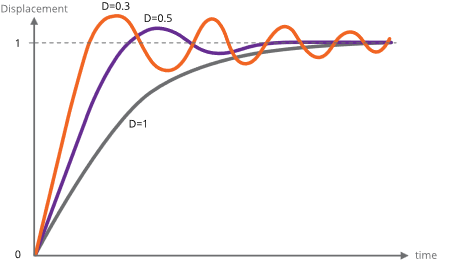
The primary (lower) resonant frequency cannot be stated with any precision, since it is modified by the friction and inertia of the load, the temperature of the motor and by the characteristics of the drive. Coupling a load inertia reduces the resonant frequency and decreases the damping factor. Load friction increases damping. Because the drive circuits of the SMD4 produce a controlled phase current this produces heavy damping. Drives which are voltage sources and which rely on the motor winding and other resistance to define the current have a lower damping factor.
The effect of changing the damping on the single step response of the motor is shown in the diagram below.
Control of resonance
The simplest method of controlling resonances is to avoid operation of the motor close to the resonant frequencies. It is usually possible to start a motor at rates in excess of 300 Hz if the load inertia is small, thereby completely avoiding the primary resonance. Resonances are not usually a problem when the motor speed is accelerating or retarding through the resonance frequency region.
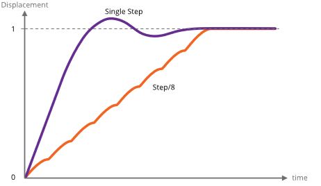
If it is necessary to operate at slow speeds or with large load inertia, using microstepping helps. It effectively increases the stepping rate by the step division factor and reduces the amplitude of the step transients that excite the resonances. This is shown in the diagram below. Because both phases are energised in microstepping there are some other processes of interchange of energy between the windings which do not occur in the single step mode and these increase the damping factor.
In particularly difficult cases, modifying the step frequency at which transition from full stepping to microstepping occurs can be helpful.
A typical motor response to a single step and to a single step subdivided into eight microsteps is shown in the diagram below.
Mechanisms for use with VCSMs
The following section is an introduction to this topic and is intended to indicate the major mechanical and vacuum considerations for various types of mechanisms. A working knowledge of mechanics and vacuum construction techniques is assumed. AML supply a range of standard mechanisms which can be customised, as well as designing custom mechanisms and components.
Rotation (Position control)
The load inertia coupled to the motor shaft should ideally be small compared to the rotor inertia of the motor. Load inertia up to two or three times that of the motor can be driven, without significant difference to the maximum start speed and acceleration which is achieved by the unloaded motor. Load inertia of around ten times that of the motor can be driven with absolute synchronism, provided care is taken over specifying the microstep and acceleration parameters. Larger inertia loads should be driven through reduction gearing.
Significant loads should have their centre of gravity on their axis of rotation, unless they are rotating in a horizontal plane.
Angular resolution at the motor shaft is limited to a single step of 1.8 °. The actual rest position within the step is determined mainly by the load friction and any torque imposed by the load on the motor at rest. If the rotor position is displaced θ° from the nominal step position, the restoring torque increases approximately in proportion to sin(100 × θ)° The maximum torque at the half step position is either the detent torque or the holding torque, depending on whether the motor is powered at rest. If the static friction and any torque due to an unbalanced load are known, this allows the rest position error to be estimated using the above approximation. The friction within the motor bearings is very low, so that a completely unloaded D42.2 motor will normally settle within 0.2 ° of the desired position if brought suddenly to rest from full stepping at 300 Hz.
Angular resolution may be improved by reduction gearing: this is discussed below.
Rotation (Speed control)
In some applications, the precise position of a rotating load is not important or can be deduced by other means, but the speed of rotation may need to be controlled very precisely. Beam choppers and sample rotators for control of deposition uniformity are applications of this type. An increased load inertia may be desirable to smooth out the stepping action of the motor. Loads of up to about 1000 times the inertia of the motor can be controlled by using long acceleration ramps. Some steps may be lost during acceleration and retardation of such loads, but precise synchronism at constant stepping frequency is easily achieved and recognised.
Significant rotating loads should be balanced, at least to the extent that the torque presented to the motor shaft is less than the detent torque of the motor. The motor torque requirement will then be dominated by that required to accelerate the load.
A typical example of a large inertia load was a 1.5 kg disk of uniform section, 20 cm in diameter. This was directly coupled to a D42.2 motor and rotated continuously in vacuum at 30 RPM.
Translation
Translation may be produced by a leadscrew and nut, wire-and-drum or rack-and-pinion mechanisms. The choice depends on the precision, length of travel, force and speed required. Leadscrew-based translators are capable of exerting forces of kilograms with resolutions of a few microns per step.
Accurate leadscrews are practical up to 400 mm long. With anti-backlash gearing between the motor and leadscrew resolution of one micron is practical. Anti-backlash nuts are not normally necessary for vertical motions. If a conventional nut is used with the leadscrew the load will be dominated by friction, especially if there is a reduction gear between the lead screw and the motor shaft which reduces the reflected load inertia.
Because of the lubrication restrictions and the slow speeds of UHV mechanisms the static friction is usually much more significant than dynamic friction. The optimum material for nuts is phosphor bronze and for lead screws is stainless steel with a diamond-like coating (DLC). DLC has a very low coefficient of friction in vacuum. Burnishing or sputtering a layer of pure Molybdenum Disulphide on the leadscrew may be useful in reducing friction and wear. The typical coefficient of friction between these materials is 0.1 and typical efficiencies are 40 % with ground trapezoidal threads. The gas load generated by frictional heating of the leadscrew is usually somewhat less than that of the motor.
The frictional losses in drum or rack drives are lower than in conventional leadscrew drives and considerations of inertia usually dominate. Rack and pinion drives are suitable for travel up to a few hundred millimetres and wire and drum mechanisms may be made several metres long. Another alternative for heavy loads is a studded stainless-steel band and matching pulleys. The repeatability and backlash of all these alternative translation drives are much worse than with screw-driven schemes.
Linear guides
Low-cost translation mechanisms can use simple bushes running on ground stainless-steel rods. A variety of carbon-reinforced polymer materials, such as PEEK, are suitable for the bushes.
'V' groove rollers and tracks and crossed-roller guides are suitable for more accurate translators. The former have the advantage of being practical to 1 metre and have minimal overall length for a given travel. Crossed-roller slides are more rigid and can support larger loads, but at higher cost. Both types have preload adjustments. 'V' rollers have smaller load-bearing surfaces and only have a rolling contact at a single point and are consequently liable to greater wear if heavily loaded. AML products of the VSM23 and VSM17 series are small-dimension examples of these types of mechanisms.
Reduction gearing
The inertia of loads coupled by reduction gearing is reduced at the motor in proportion to the square of the reduction ratio. Where reduction gearing is used for load matching, the spur gear meshing with the motor pinion will normally dominate the load inertia and it is important to keep its diameter small. Anti-backlash gears and standard pinions should be used in the gear train to damp any resonances in the mechanism. Gears for use in UHV should be designed for low friction without lubrication and with dissimilar materials in contact to avoid cold-welding. Nitrogen ion-implantation of the rolling surfaces or complete Titanium Nitride coating of gears are effective means of achieving this and other desirable properties in all-stainless-steel gear trains.
Bearings
Bearings for use in UHV should be unshielded and have a stainless steel cage and race. The balls should be either stainless steel coated with some other material or solid ceramic. As an alternative, all-stainless bearings having a PTFE composite component in the race (which is designed to transfer to the balls) are also suitable.
Magnetic fields near motor
Motors should not be operated in fields of greater than 50 millitesla (500 gauss), as this will affect the performance while the field is present. Fields significantly greater than this may cause partial demagnetisation of the rotor, reducing the torque. Demagnetised motors can be restored by AML.
The leakage field of a motor is of the order of 1 millitesla (10 gauss) at 1 cm from the cylindrical surface of the motor in an axial direction and is present when the motor is not powered. Under drive an alternating component is added at the step frequency and its harmonics up to a few kHz. The field is easy to screen with Mu-metal or similar high permeability foil to below a few milligauss at the sides of the motor but is more difficult around the projection of the shaft. Early consideration of the interaction of stray fields on nearby equipment is recommended.
Low power techniques
In the design of small mechanisms there are several factors that are not accurately known, or that have poor tolerances, for which generous allowances must be made. The result should be a conservative design where the available torque is in excess of the requirement. Some of this excess can be exchanged for increased running time or decreased outgassing in vacuum by various techniques. Used in combination the improvement can be very significant.
Most of the 'tuning' procedures below require the motor or mechanism to be run on the bench under realistic representative operating conditions while adjusting a parameter to the point where normal stepping operation fails. Erratic stepping is easy to see; a cable tie on the motor shaft makes a useful pointer. Familiarity with the SMD4 software and or remote interface is assumed.
Techniques applicable to all applications
- Run the motor at stepping rates between 500 Hz and 2 kHz, where its electromechanical efficiency is greatest, if possible
- Reduce the acceleration for inertia-dominated loads
- Reduce the phase current progressively to about 20% more than the minimum for consistent stepping. Some adjustment of the acceleration parameters may be needed
- Make use of the run and acceleration current settings; try a higher current during acceleration to overcome inertia of a large load, and the minimum current possible during run to keep the load moving. This will reduce motor power dissipation versus using the same higher current all the time
- Improve the heatsinking arrangements. A reduction in motor temperature decreases the winding resistance and increases its efficiency.
Techniques where step rates less than 100 Hz
For applications where operation below few hundred steps per second is satisfactory, use the following technique beyond those above. The desired effect is to complete each step as quickly as possible and remove or reduce the power to the minimum as soon as possible. Each step is completed in a few milliseconds, so that the power saving is progressively greater at lower speeds. Read and ensure that you understand the complete procedure before starting.
Set the target frequency VMAX equal to the start speed VSTART and steadily increase them both to determine the highest speed at which the motor will start. Take care when increasing the speed through the expected resonance range because the motor may not start in that range, although it may start reliably at higher speeds.
Configure PDDEL, IHD and IH to zero, to reduce motor current to zero as quickly as possible after each step is completed. Move the motor in single steps at the highest reliable starting speed, followed by a delay of a few milliseconds or more. This reduces power dissipation in the motor and so minimises temperature rise. It also has the consequence of reducing the damping factor at the time the power is reduced, so some experimentation with the parameters is required to ensure an adequate margin of stability is obtained.
Possible causes of damage to VCSMs
Vacuum motors must be de-magnetised before disassembly and re-magnetised and cleaned after repair. For these reasons most will need to be returned to AML for repair. The notes below offer guidance on the avoidance of the most common problems and diagnostic advice.
Bearing damage
The ceramic balls in the bearings are very strong but more brittle than steel balls. Dropping the motor on its end will probably break some balls. The damage is occasionally visible and any roughness felt when rotating the shaft manually will indicate that this has happened.
Debris inside the motor
Foreign material can enter the motor via the pumping holes and gaps in the bearings. Particles of magnetic materials are particularly likely to be attracted through the pumping holes and they eventually migrate into the gap between the rotor and stator. They usually cause the rotor to stick at one or more points per revolution and can often only be felt when rotating in a specific direction. Fortunately, the larger motors have enough torque to grind them into a dust.
The main cause of this type of problem has been users modifying shafts. This can be avoided by sealing the motor inside a cleaned polyethylene bag and supervising the machining closely. Clean the projecting shaft and remove magnetic particles with a magnet before opening the bag. Remove the motor or similarly seal it if any filing or drilling of nearby components is done.
Overheating
Motors which have been heated to 230 °C will produce a much greater gas load thereafter, although their electromechanical performance may not be affected. In extreme cases, the insulating material will ablate and deposit itself as a yellow powder inside the motor case and on any cool surfaces in line with the pumping holes.
Motors can overheat very quickly in vacuum. This is very unlikely to happen with a properly connected SMD4 drive. Never use a drive capable of providing more than 1 amp of phase current and ensure that the drive current is removed as soon as the indicated temperature exceeds 190 °C. This is performed automatically by the SMD4.